A machine has many moving parts. Some machines have balancing of rotating masses motion and some of them have reciprocating motion. If these moving parts are not in complete balance, inertia forces are set up which may cause excessive noise, vibration, wear and tear of the system.
Thus, balancing is the process of designing or modifying machinery so that the unbalance is reduced to an acceptable level and if possible is eliminated entirely.
When a particle or mass moving in a circular path, it experiences a centripetal force acting radially inwards. An equal and opposite force acting radially outwards on the axis of rotation and is known as centrifugal force. This is a disturbing force, and its magnitude remains constant but the direction changes with the rotation of the mass.
The centrifugal disturbing force, Fc = m ω² r
where, m = Mass of the rotating component in kg,
ω = Angular velocity of the component in rad/s = 2πN/60,
N = Speed of the component in r.p.m., and
r = Distance of C.G of mass from the axis of rotation in metres.
In fact, due to modern trend of development of high speed machines and vehicles, the problem of balancing becomes greater importance for mechanical engineers. This type of unbalance problem is very common in steam turbine rotors, engine crankshafts, rotary compressors, centrifugal pumps.
Types of Balancing
Study of the problem of balancing can be divided into two classes :
- Balancing of rotating masses, and
- Balancing of reciprocating masses.
The balancing of rotating parts of machines are considered.
Balancing of Single Rotating Mass
Consider a mass of m attached to shaft rotating at ω rad/s, as shown in Fig(a). Let r be the radius of rotation (distance between the axis of rotation of the shaft and the C.G of the mass m) of the mass ‘m’.
We know that the centrifugal force (disturbing force) Fc = m ω² r, producing out of balance effect acting radially outwards on the shaft. This out of balance force can be balanced in any one of the following two ways.
By Introducing Single Revolving Mass in the Same Plane
The disturbing mass m is balanced by introducing a counter mass or balancing mass mb at radius of rotation rb diametrically opposite to m in the same plane, rotating with same angular velocity ω rad/s, as shown in Fig(b)
Note : The product mb rb or m r is very often called as the mass moment.
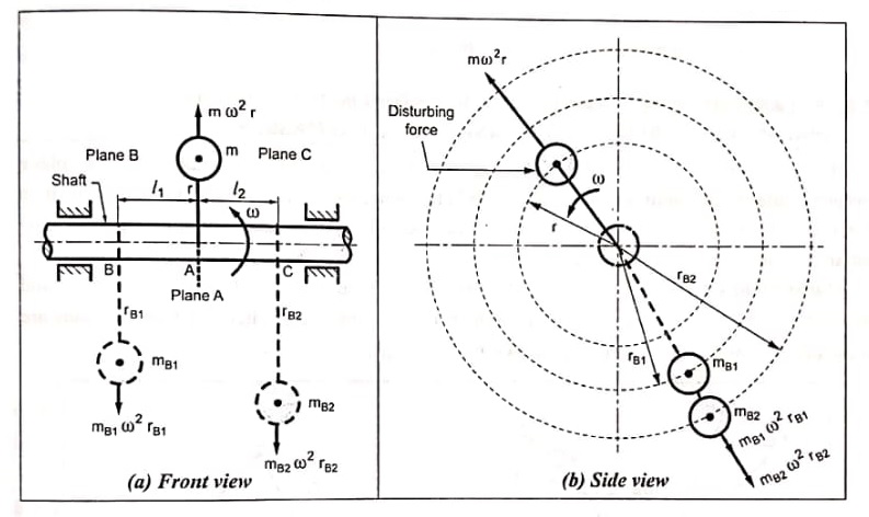
By Introducing Two Revolving Masses in Different Planes
Sometimes it is not possible to introduce balancing mass in the same plane in which disturbing mass m is placed. In that case two masses can be placed in different planes.
If the balancing mass and disturbing mass lie in different planes, disturbing mass cannot be balanced by a single mass as there will be a couple left unbalanced.
In such cases, at least two balancing masses are required for complete balancing and the three masses are arranged in such a way that the resultant force and couple on the shaft are zero, as shown in Fig.
| Read More Topics |
| Types of balancing machines |
| Wind power plant |
| Types of electrical braking |
[sc_fs_faq html=”true” headline=”h2″ img=”” question=”Why rotating masses are to be dynamically balanced?” img_alt=”” css_class=””] If the rotating are not dynamically balanced, the unbalanced dynamic forces will cause worse effects such as wear and tear on bearings and excessive vibrations on machines. It is very common in cam shafts, steam turbine rotors, engine crank shafts, and centrifugal pumps. [/sc_fs_faq]