To find out the accuracy of a screw thread, it will be necessary to measure the following:
- Major diameter
- Minor diameter
- Effective or Pitch diameter
- Pitch
- Thread angle and form
Measurement of major diameter
The instruments which are used to find the major diameter are
- Ordinary micrometer
- Bench micrometer.
Ordinary micrometer:
The ordinary micrometer is quite suitable for measuring the external major diameter. It is first adjusted for appropriate cylindrical size (S) having the same diameter (approximately).
This process is known as ‘gauge setting’. After taking this reading ‘R1‘, the micrometer is set on the major diameter of the thread, and the new reading is ‘R2‘.
Then the major diameter, D = S± (R1 – R2)
S = Size of setting gauge
R1 = Micrometer reading over setting gauge.
R2 = Micrometer reading over thread.
Bench micrometer:
For getting the greater accuracy, the bench micrometer is used for measuring the major diameter. In this process, the variation is measured.
Pressure, pitch errors are being neglected. From the above fig the fiducial indicator is used to ensure all the measurements are made at the same pressure.
The instrument has a micrometer head with a vernier scale to read the accuracy of 0.002mm. Calibrated setting cylinder having the same diameter as the major diameter of the thread to be measured is used as a setting standard. After setting the standard, the setting cylinder is held between the anvils and the reading is taken.
Then the cylinder is replaced by the threaded work piece and the new reading is taken.
∴The major diameter of screw thread = S± (R2 – R1)
Where, S = Diameter of the setting cylinder.
R2 = Micrometer Reading on screw thread
R1 = Micrometer reading on setting cylinder.
Measurement of the major diameter of an internal thread:
The internal thread major diameter is usually measured by thread comparator fitted with ball-ended stylii.
Initially, the Instrument is set for a cylindrical reference having the same diameter of major diameter of internal thread and the reading is taken. Then the floating head is retracted to engage the tip of the stylii at the root of spring under pressure. For that, the new reading is taken.
The major diameter of internal thread = D ± (R2 – R1)
Where, D = Cylindrical standard diameter
R2 = Thread reading
R1 = Dial Indicator reading on the standard.
Measurement of minor diameter
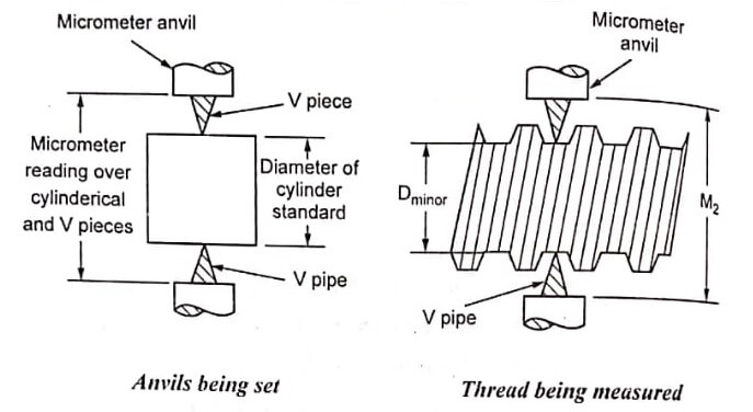
The minor diameter is measured by a comparative method using floating carriage diameter measuring machine and small ‘V’ pieces which make contact with the root of the thread.
These V pieces are made in several sizes, having suitable radii at edges. The V pieces are made up of hardened steel. The floating carriage diameter measuring machine is a bench micrometer mounted on a carriage.
Measurement process:
The threaded work piece is mounted between the centers of the instrument and the V pieces are placed on each side of the work piece and for that position the reading is noted. After taking, readings the work piece is replaced by a standard reference cylindrical setting gauge.
The minor diameter of the thread = D ± (R2 – R1)
Where, D = Diameter of cylindrical gauge
R2= Micrometer reading on threaded work piece.
R1 = Micrometer reading on cylindrical gauge.
Measurement of minor diameter of internal threads:
The minor diameter of internal threads are measured by
- Using taper parallels
- Using Rollers.
Using taper parallels:
For diameters less than 200mm, the use of Taper parallels and micrometer are very common. The taper parallels are pairs of wedges having reduced and parallel outer edges. The diameter across their outer edges can be changed by sliding them over each other.
The taper parallels are inserted inside the thread until firm contact is established with the minor diameter. The outer diameter is measured with a micrometer.
Using rollers:
For more than 20mm diameter, this method is used. Precision rollers are inserted inside the thread and proper slip gauge is inserted between the rollers. The minor diameter is then the length of slip gauges plus twice the diameter of roller.
Measurement of effective diameter (D2)
The effective diameter measurement is carried out by the following methods.
One wire, two wires, or three wires method, micrometer method.
One wire method:
In this method, only one wire is used. The wire is placed between the two threads at one side and on the other side the anvil of the measuring micrometer contacts the crests.
First, the micrometer reading d1 is noted on a standard gauge whose dimension is approximately same to be obtained by this method. Now, the setting gauge is replaced by thread and the new reading is taken i.e. ‘d2‘ then effective diameter = D ± (d1 – d2)
When D= Size of setting gauge.
Actual measurement over wire on one side and threads on other side = size of gauge ± difference in two micrometer readings.
Two wire method:
Two wire method of measuring the effective diameter of a screw thread is given below. In this method, wires of suitable size are placed between the standard and the micrometer anvils.
First, the micrometer reading is taken and let it be R1. Then the standard is replaced by the screw thread to be measured and the new reading is taken. The new reading is R2.
From the above reading,
Effective diameter E is calculated by E = T + P
Where, T = Dimension under the wires = M – 2d
M = Dimension over the wires
d= diameter of each wire
If P’ = Pitch of thread then
P = 0.9605 P’ – 1.1657d = Whitworth thread.
P = 0.866 P’ – d For metric thread.
Here, P = the difference between the effective diameter and the diameter under the wires.
- See More : Measurements of screw threads
- See More : Vertical axis wind turbine
- See More : Types of solar collectors
- See More : Ocean Thermal Energy Conversion
