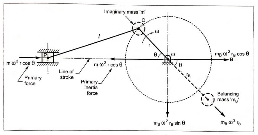
Consider a reciprocating engine mechanism OCP shown in Fig, the piston mass at P of the reciprocating parts is accelerating. Thus a primary force is required to accelerate the reciprocating mass. This force acts in a direction from P to O. The reaction of this force tends to move the frame in a direction from O to P But this is not desirable. So to prevent this, we have to balance this reaction i.e., primary unbalanced force (m ω² r cos θ), as below.
Step 1 : Treat the primary unbalanced force m ω² r cos θ as the component of centrifugal force produced by an imaginary rotating mass m placed at crank pin C, as shown in Fig. Since the primary unbalanced force acts along the line of stroke, balancing of primary unbalanced force can be considered as equivalent to balancing of mass rotating at the crank radius r.
Step 2 : Now similar to the balancing of rotating masses, add a rotating countermass mB at radius rB diametrically opposite to the crank pin C.
We know that centrifugal force due to mass mB = mB ω² rB
Its two components are:
- Horizontal component mB ω² rB cos θ, acting towards right, and
- Vertical component mB ω² rB sin θ, acting vertically downwards.
The reaction due to primary force (m ω² r cos θ) is balanced, if mB ω² rB cos θ = m ω² r cos θ or mBrB = m r
But the balancing mass mB also has a component mB ω² rB sin θ perpendicular to the line of stroke which remains unbalanced. This unbalanced force is zero at θ = 0° and 180° which are the end of the stroke. This unbalanced force is maximum when θ = 90° and 270°, which is same as the maximum value of primary unbalanced force m ω² r.
Due to this vertical unbalanced force, the mechanism tends to jump up and down instead of to and fro sliding motion. To minimise the effect of the unbalanced force, in actual practice, a compromise is made that only a fraction of reciprocating masses is balanced, such that
c m r = mB rB
where c = Fraction of the reciprocation mass is to be balanced.
∴ Unbalanced force along the line of stroke is given by
FHU = m ω² r cos θ – mB ω² rB cos θ
= m ω² r cos θ – c m ω² rB cos θ [∵ mB rB = c m r]
= (1 – c) m ω² r cos θ
and unbalanced force along the perpendicular to the line of stroke is given by
FVU = mB ω² rB sin θ = c m ω² r sin θ
∴ Resultant unbalanced force at any instant is given by
![Rendered by QuickLaTeX.com \begin{aligned} \mathrm{F}_{\mathrm{RU}} &=\sqrt{\left(\mathrm{F}_{\mathrm{HU}}\right)^{2}+\left(\mathrm{F}_{\mathrm{VU}}\right)^{2}} \\ &=\sqrt{\left[(1-c) m \omega^{2} r \cos \theta\right]^{2}+\left[c m \omega^{2} r \sin \theta\right]^{2}} \end{aligned}](https://pedagogyzone.com/wp-content/ql-cache/quicklatex.com-517d447ea7b649a28dfdf4ed70baf4bf_l3.png)
or
![]()
- See More : Balancing of rotating masses
- See More : Wind power plant
- See More : High energy rate forming process


