The topic of robot dynamics is concerned with the analysis of the torques and forces due to acceleration and deceleration. Torques experienced by the joints due to acceleration of the links, as well as forces experienced by the links due to torques applied by the joints, are included within the scope of dynamic analysis.
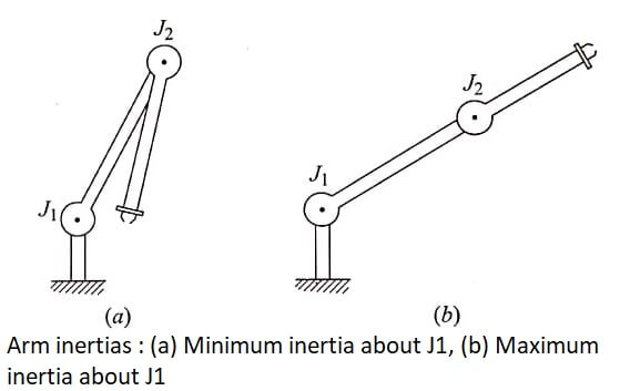
Solving for the accelerations of the links is difficult due to a number of factors. For one, the acceleration is dependent on the inertia of the arm.
However, the inertia is dependent on the configuration of the arm, and this is continually changing as the joints are moved. An additional factor that influences the inertia is the mass of the payload and its position with respect to the joints.
This also changes as the joints are moved. Figure shows the two-link arm in the maximum and minimum inertia configurations.

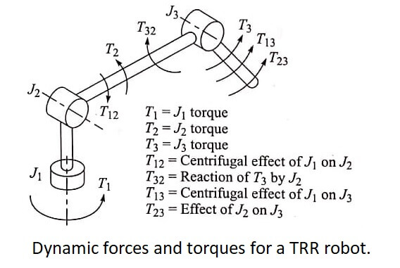
The torques required to drive the robot arm are not only determined by the static and dynamic forces described above; each joint must also react to the torques of other joints in the manipulator, and the effects of these reactions must be included in the analysis.
Also, if the arm moves at a relatively high speed, the centrifugal effects may be significant enough to consider. The various torques applied to the two-jointed manipulator are illustrated in figure.

The picture becomes substantially more complicated as the number of joints is increased.
Dynamics – There are many different approaches to computing the dynamics of a robot arm. In this section we will briefly discuss about the Newton-Euler method and the Euler-Lagrangian formulation.
The newton-Euler method is a ‘force balance’ approach while the Euler-Lagrangian approach is an ‘energy-based’ approach.
In the Newton-Euler formulation we are required to first compute the linear and angular accelerations of the mass centres of each link. Then the inertia forces and torques acting at the centre of each link is calculated as:
![]()
where Fi is the force and Ni is the torque (moment) acting at the mass centre of each link ‘i‘, vi and wi are the linear velocity and angular velocity of each link centre ‘I’ is the inertia tensor of each link. After computing all the forces and moments the torques acting at each joint is found by taking the Z component of the torque ‘τ’ applied by one link on the other.
τi = Ni Zi
In the Lagrangian formulation we derive the equation of motion using a scalar function called the Lagrangian, which is the difference between the kinetic and potential energies of each link. The scalar Lagrangian function is written as
L = KE – PE
where KE and PE are the kinetic and potential energies of the link. The kinetic energy of a link is given as
![]()
While the potential energy of the link is given by
PE = -mg Pi
where ‘g’ is the gravity vector that normally points downwards hence the negative sign, and Pi is the position of the centre of the link.
The equation of motion of the manipulator is then derived from by
![]()
where ‘τ’ is the vector of joint torques. Using the Lagrangian formulation the final equation of motion takes the form.
![]()
where
D(θ)θ¨ = inertia forces
H(θ,θ˙) = corioles and centrifugal forces
C (θ) = gravity forces
F = joint friction or external forces.
Normally a computer program is required to find the dynamic torques of a large manipulator.
| Read More Topics |
| Robot programming and work cell |
| Robot drive system |
| Types of robot control |
| Robot sensors and actuators |


