This and the following sections of this chapter will examine the programming issues involved in the use of the lead through methods, with emphasis on the powered lead through approach.
Let us begin our discussion with our previous definition of a robot program as a path in space. The locus of points along the path defines the sequence of positions through which the robot will move its wrist.
In most applications, an end effector is attached to the wrist, and the program can be considered to be the path in space through which the end effector is to be moved by the robot.
Since the robot consists of several joints (axes) linked together, the definition of the path in space in effect requires that the robot move its axes through various positions in order to follow that path.
For a robot with six axes, each point in the path consists of six coordinate values. Each coordinate value corresponds to the position of one joint.
There are four basic robot anatomies: polar, cylindrical, cartesian, and jointed arm. Each one has three axes associated with the arm and body configuration and two or three additional joints associated with the wrist.
The arm and body joints determine the general position in space of the end effector and the wrist determines its orientation.
If we think of a point in space in the robot program as a position and orientation of the end effector, there is usually more than one possible set of joint coordinate values that can be used for the robot to reach that point.
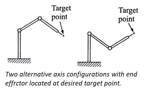
For example, there are two alternative axis configurations that can be used by the jointed-arm robot shown in fig to achieve the target point indicated.
We see in the figure that although the target point has been reached by both of the alternative axis configurations, there is a difference in the orientation of the wrist with respect to the point.
We must conclude from this that the specification of a point in space does not uniquely define the joint coordinates of the robot.
Conversely, however, the specification of the joint coordinates of the robot does define only one point in space that corresponds to that set of coordinate values. Points specified in this fashion are said to be joint coordinates.
Accordingly, let us refine our definition of a robot program by specifying it to be a sequence of joint coordinate positions, rather than merely a path in space.
An advantage of defining a robot program in this way is that it simultaneously specifies the position and orientation of the end effector at each point in the path.

Let us consider the problem of defining a sequence of points in space. We will assume that these points are defined by specifying the joint coordinates as described above, although this method of specification will not affect the issues we are discussing here.
For the sake of simplicity, let us assume that we are programming a point-to-point Cartesian robot with only two axes, and only two addressable points for each axis.
An addressable point is one of the available points (as determined by the control resolution) that can be specified in the program so that the robot can be commanded to go to that point.
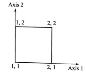
Figure shows the four possible points in the robot’s rectangular workspace. A program for this robot to start in the lower left-hand corner and traverse the perimeter of the rectangle could be written as follows:

| Step | Move | Comment |
| 1 | 1,1 | Move to lower left corner |
| 2 | 2,1 | Move to lower right corner |
| 3 | 2,2 | Move to upper right corner |
| 4 | 1,2 | Move to upper left corner |
| 5 | 1,1 | Move back to start position |
The point designation correspond to the x,y coordinate positions in the cartesian axis system, as illustrated in the figure. In our example, using a robot with two orthogonal slides and only two addressable points per axis, the definition of points in space corresponds exactly with joint coordinate values.
Using the same robot, let us consider its behavior when performing the following program:
| Step | Move | Comments |
| 1 | 1,1 | Move to lower left corner |
| 2 | 2,1 | Move to lower right corner |
| 3 | 1,2 | Move to upper left corner |
| 4 | 1,1 | Move back to start position |
The second program is the same as the first, except that the point in the upper right comer (2,2) has not been listed.
Before explaining the implications of this missing point, let us recall that in Example before table, the move from one point to the next required only one joint to be moved while the other joint position remained unchanged.
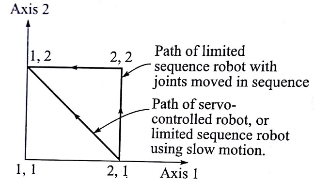
In this second program, the move from point 2,1 to point 1,2 requires both joints to be moved. The question that arises is what path will the robot follow in getting from the first point to the second? Certainly one possibility is that both axes will move at the same time, and the robot will therefore trace a path along the diagonal line between the two points.
The other possibility is that the robot will move only one axis at a time and trace out a path along the border of the rectangle, either through point 2,2 or through point 1,1.
The question of which path the robot will take between two programmed points is not a trivial one. It is important for the programmer to know the answer in order to plan out the motion path correctly.
Unfortunately, there is no general rule that all robots follow. Limited-sequence non-servo robots, which are programmed using manual setup procedures rather than lead through methods, can usually move both joints at the same time.
Therefore, the path that is followed involves a slow motion which is along the diagonal in our illustration. Other limited sequence robots move their joints in sequence rather than simultaneously.
Usually, these robots that move one axis at a time do so by moving the lower numbered axes first. Thus, the path through point 2,2 is most likely in this example.
However, there are no industry standards on this issue, and the programmer must make this kind of determination either from the user’s manual or by experimentation with the actual robot.
Servocontrolled robots, which are programmed by lead through and textual language methods, tend to actuate all axes simultaneously.
Hence, with servocontrol, the robot would likely move approximately along the diagonal path between points 2,1 and 1,2 . The differences between the paths for Example table are illustrated in fig.
As illustrated by the preceding discussion of Example table, it is possible for the programmer to make certain types of robots pass through points without actually including the points in the program.

The key phrase is ‘pass through.’ These are not addressable points in the program and the robot will not actually stop at them in the sense of an addressable point.
| Read More Topics |
| Types of robot control |
| Robot arm dynamics |
| Robot programming and work |
| Configuration of robot controller |


