Anytime a host or a router has an IP datagram to send to another host or router, it has the logical (IP) address of the receiver. But the IP datagram must be encapsulated in a frame to be able to pass through the physical network. This means that the sender needs the physical address of the receiver.
A mapping corresponds a logical address to a physical address. Figure shows the position of the ARP in the TCP/IP protocol suite. ARP accepts a logical address from the IP protocol, maps the address to the corresponding physical address and pass it to the data link layer.

ARP associates an IP address with its physical address. On a typical physical network, such as a LAN, each device on a link is identified by a physical or station address that is usually imprinted on the NIC.
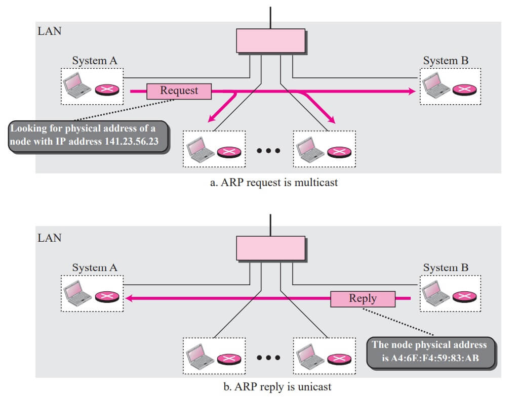
Anytime a host, or a router, needs to find the physical address of another host or router on its network, it sends an ARP query packet. The packet includes the physical and IP addresses of the sender and the IP address of the receiver. Because the sender does not know the physical address of the receiver, the query is broadcast over the network.
Every host or router on the network receives and processes the ARP query packet, but only the intended recipient recognizes its IP address and sends back an ARP response packet. The response packet contains the recipient’s IP and physical addresses. The packet is unicast directly to the inquirer using the physical address received in the query packet.
In figure a, the system on the left (A) has a packet that needs to be delivered to another system (B) with IP address 141.23.56.23. System A needs to pass the packet to its data link layer for the actual delivery, but it does not know the physical address of the recipient. It uses the services of ARP by asking the ARP protocol to send a broadcast ARP request packet to ask for the physical address of a system with an IP address of 141.23.56.23.

This packet is received by every system on the physical network, but only system B will answer it, as shown in figure b. System B sends an ARP reply packet that includes its physical address. Now system A can send all the packets it has for this destination using the physical address it received.
Packet Format
Figure shows the format of an ARP packet. The fields are as follows:
Hardware type – This is a 16-bit field defining the type of the network on which ARP is running. Each LAN has been assigned an integer based on its type. For example, Ethernet is given the type 1. ARP can be used on any physical network.
Protocol type – This is a 16-bit field defining the protocol. For example, the value of this field for the IPv4 protocol is 080016. ARP can be used with any higher-level protocol.
Hardware length – This is an 8-bit field defining the length of the physical address in bytes. For example, for Ethernet the value is 6.
Protocol length – This is an 8-bit field defining the length of the logical address in bytes. For example, for the IPv4 protocol the value is 4.
| Hardware Type | Protocol Type | |
| Hardware length | Protocol length | Operation Request 1, Replay 2 |
| Sender hardware address (For example, 6 bytes for Ethernet | ||
| Sender protocol address (For example, 4 bytes for IP) | ||
| Target hardware address (For example, 6 bytes for Ethernet) (It is not filled in a request) | ||
| Target protocol address (For example, 4 bytes for IP) | ||
Operation – This is a 16-bit field defining the type of packet. Two packet types are defined: ARP request (1), ARP reply (2).
Sender hardware address – This is a variable-length field defining the physical address of the sender. For example, for Ethernet this field is 6 bytes long.
Sender protocol address – This is a variable-length field defining the logical (for example, IP) address of the sender. For the IP protocol, this field is 4 bytes long.
Target hardware address – This is a variable length field defining the physical address of the target. For example, for Ethernet this field is 6 bytes long. For an ARP request message, this field is all 0s because the sender does not know the physical address of the target.
Target protocol address – This is a variable-length field defining the logical (for example, IP) address of the target. For the IPv4 protocol, this field is 4 bytes long.
Encapsulation
An ARP packet is encapsulated directly into a data link frame. For example, in Figure an ARP packet is encapsulated in an Ethernet frame. Note that the type field indicates that the data carried by the frame is an ARP packet.
Operation
Let us see how ARP functions on a typical internet. First we describe the steps involved. Then we discuss the four cases in which a host or router needs to use ARP.
Steps Involved
These are seven steps involved in an ARP process:
1. The sender knows the IP address of the target. We will see how the sender obtains this shortly.
2. IP asks ARP to create an ARP request message, filling in the sender physical address, the sender IP address, and the target IP address. The target physical address field is filled with 0s.

3. The message is passed to the data link layer where it is encapsulated in a frame using the physical address of the sender as the source address and the physical broadcast address as the destination address.
4. Every host or router receives the frame. Because the frame contains a broadcast destination address, all stations remove the message and pass it to ARP. All machines except the one targeted drop the packet. The target machine recognizes the IP address.
5. The target machine replies with an ARP reply message that contains its physical address. The message is unicast.
6. The sender receives the reply message. It now knows the physical address of the target machine.
7. The IP datagram, which carries data for the target machine, is now encapsulated in a frame and is unicast to the destination.
An ARP request is broadcast; an ARP reply is unicast.
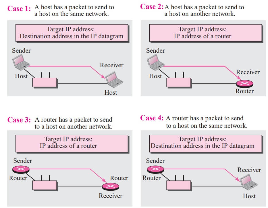
The following are four different cases in which the services of ARP can be used (see Figure).
Case 1 : The sender is a host and wants to send a packet to another host on the same network. In this case, the logical address that must be mapped to a physical address is the destination IP address in the datagram header.
Case 2 : The sender is a host and wants to send a packet to another host on another network. In this case, the host looks at its routing table and finds the IP address of the next hop (router) for this destination. If it does not have a routing table, it looks for the IP address of the default router. The IP address of the router becomes the logical address that must be mapped to a physical address.
Case 3 : The sender is a router that has received a datagram destined for a host on another network. It checks its routing table and finds the IP address of the next router. The IP address of the next router becomes the logical address that must be mapped to a physical address.
Case 4 : The sender is a router that has received a datagram destined for a host in the same network. The destination IP address of the datagram becomes the logical address that must be mapped to a physical address.

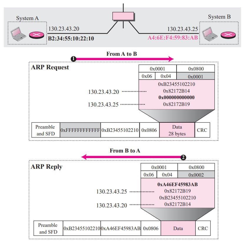
Example : A host with IP address 130.23.43.20 and physical address B2:34:55:10:22:10 has a packet to send to another host with IP address 130.23.43.25 and physical address A4:6E:F4:59:83:AB (which is unknown to the first host). The two hosts are on the same Ethernet network. Show the ARP request and reply packets encapsulated in Ethernet frames.
Solution : Figure shows the ARP request and reply packets. Note that the ARP data field in this case is 28 bytes, and that the individual addresses do not fit in the 4-byte boundary. That is why we do not show the regular 4-byte boundaries for these addresses. Also note that the IP addresses are shown in hexadecimal. For information on binary or hexadecimal notation see Appendix B.
Proxy ARP
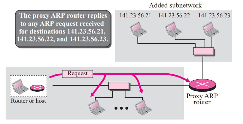
A technique called proxy ARP is used to create a subnetting effect. A proxy ARP is an ARP that acts on behalf of a set of hosts. Whenever a router running a proxy ARP receives an ARP request looking for the IP address of one of these hosts, the router sends an ARP reply announcing its own hardware (physical) address. After the router receives the actual IP packet, it sends the packet to the appropriate host or router.
Let us give an example. In Figure the ARP installed on the right-hand host will answer only to an ARP request with a target IP address of 141.23.56.23.


However, the administrator may need to create a subnet without changing the whole system to recognize subnetted addresses. One solution is to add a router running a proxy ARP. In this case, the router acts on behalf of all of the hosts installed on the subnet. When it receives an ARP request with a target IP address that matches the address of one of its protégés (141.23.56.21, 141.23.56.22, and 141.23.56.23), it sends an ARP reply and announces its hardware address as the target hardware address. When the router receives the IP packet, it sends the packet to the appropriate host.
| Read More Topics |
| Address mapping in computer networks |
| Introduction to internet protocol |
| Delivery and forwarding of IP packets |
| The user datagram protocol (UDP) |
| Class template with overloaded operators |


