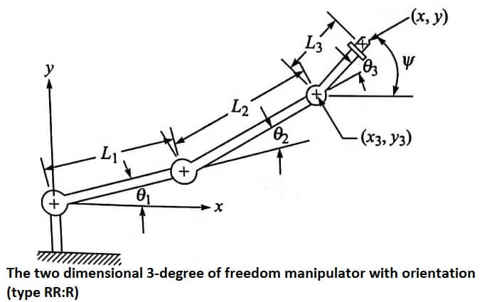
The arm we have been modeling is very simple; a two-jointed robot arm has little practical value except for very simple tasks. Let us add to the manipulator a modest capability for orienting as well as positioning a part or tool.
Accordingly, we will incorporate a third degree of freedom into the previous configuration to develop the RR:R manipulator shown in fig.
This third degree of freedom will represent a wrist joint. The world space coordinates for the wrist end would be
x = L1 cos θ1 + L2 cos (θ1 + θ2) + L3 cos (θ1 + θ2 +θ3)
y = L1 sin θ1 + L2 sin (θ1 + θ2) + L3 sin (θ1 + θ2 +θ3)
Ψ = (θ1 + θ2 +θ3)
We can use the results that we have already obtained for the 2-degree of freedom manipulator to do the reverse transformation for the 3 -degree of freedom arm.
When defining the position of the end of the arm we will use x,y, and Ψ. The angle Ψ is the orientation angle for the wrist. Given these three values, we can solve for the joint angles (θ1, θ2, and θ3) using
x3 = x – L3 cos Ψ
y3 = y – L3 sin Ψ
Having determined the position of joint 3, the problem of determining θ1 and

θ1 reduces to the case of the 2-degree of freedom manipulator previously analyzed.
| Read More Topics |
| Configuration of robot control |
| Robot sensors and actuators |
| Types of robot control |


