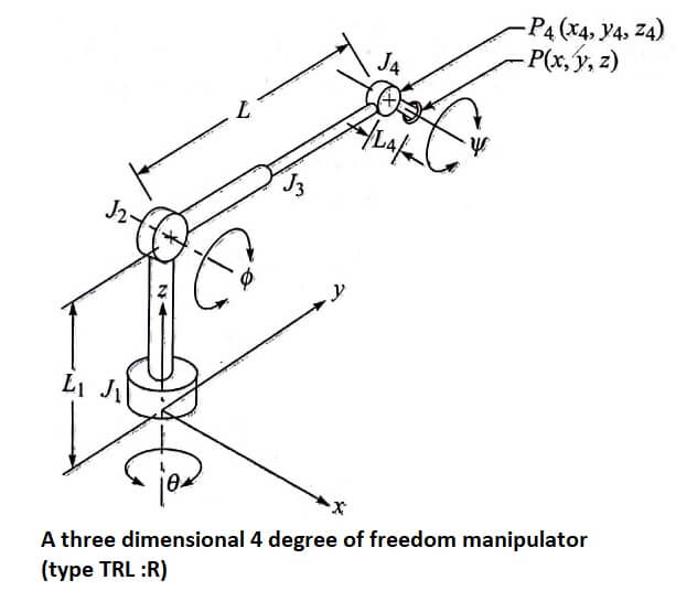
Figure illustrates the configuration of a manipulator in three dimensions. The manipulator has 4 degrees of freedom: joint 1 (type T joint) allows rotation about the z axis; joint 2 (type R) allows rotation about an axis that is perpendicular to the z axis; joint 3 is a linear joint which is capable of sliding over a certain range; and joint 4 is a type R joint which allows rotation about an axis that is parallel to the joint 2 axis. Thus, we have a TRL: R manipulator.
Let us define the angle of rotation of joint 1 to be the base rotation θ; the angle of rotation of joint 2 will be called the elevation angle Φ; the length of linear joint 3 will be called the extension L (L represents a combination of links 2 and 3); and the angle that joint 4 makes with the x-y plane will be called the pitch angle Ψ.
The position of the end of the wrist, p, defined in the world coordinate system for the robot, is given by
x = cos θ(L cos Φ + L4 cos Ψ)
y = sin θ(L cos Φ + L4 cos Ψ)
z = L1 + L sin Φ + sin Ψ
Given the specification of point P (x,y,z) and pitch angle Ψ, we can find any

of the joint positions relative to the world coordinate (x4,y4,z4), which is the position of joint 4, as an example,
x = x – r cos θ (L4 cos Ψ)
y4 = y – sin θ (L4 cos Ψ)
z4 = z – L4 sin Ψ
The values of L, Φ, and θ can next be computed:
![Rendered by QuickLaTeX.com \begin{aligned} L &=\left[x_{4}^{2}+y_{4}^{2}+\left(z_{4}-L_{1}\right)^{2}\right]^{-1} \\ \sin \phi &=\frac{z_{4}-L_{1}}{L} \\ \cos \theta &=\frac{y_{4}}{L} \end{aligned}](https://pedagogyzone.com/wp-content/ql-cache/quicklatex.com-bde5eaccd2cc97144cd29c745a7f2f45_l3.png)
The example we have just done is simple but not unrealistic. In order for a robot controller to be able to perform the calculations necessary quickly enough to maintain good performance they must be kept as simple as possible.
The manipulator kinematics described in this example are very similar to those of the MAKER robot, by U.S. Robots. The only real difference is that the MAKER’s wrist mechanism has more than a single joint.
One facet of our approach in the preceding analysis which should be noted by the reader is that we separated the orientation problem from the positioning problem.
This approach of separating the two problems greatly simplifies the task of arriving at a solution.
| Read More Topics |
| Configuration of a robot controller |
| Robot drive system |
| Robot sensors and actuators |
| Electrostatic sensors and actuators |


