Principle
When ultrasonic waves are passed through a liquid, it density varies from layer to layer. This happen due to periodic variation of pressure. Under this condition, when monochromatic light is passed through the liquid at right angle to the waves, the liquid causes the light to behaves as a diffraction grating. Such a grating is called acoustic grating.
By using the condition for diffraction, the velocity of ultrasonic waves can be determined.
In 1932, Debye and Shears first observed the phenomenon of diffraction of light by ultrasonic waves.
Construction
The set up has a transparent glass tank containing a liquid (kerosene). There is a piezo-electric crystal at the bottom of the rectangular glass tank, which is connected to an oscillating circuit. The crystal is placed in such a manner that it hangs parallel to one side of the vessel. A monochromatic light source, a telescope and a collimator with two lens L1 and L2 are used.
Working
- The ultrasonic waves are produced by the quartz crystal. These waves are passed through the liquid medium in a glass tank and get reflected from the opposite side of the vessel.
- The incident and reflected waves get superimposed forming longitudinal stationary waves in the liquid medium. These stationary waves give rise to fixed pattern of nodal and antinodal planes.
- At the nodal planes the density of the liquid becomes more and hence the refractive index is maximum, while at the antinodal planes the density of the liquid becomes less and hence the refractive index is minimum.
- The variations in the refractive index of the medium due to ultrasonic propagation act similar to diffraction grating is called acoustic grating.

Fig.1.1. Experimental setup for the formation of acoustic grating
A parallel beam of monochromatic light from a collimator is incident normally on the acoustic grating. A diffraction pattern consisting of central maximum from the direct beam and first order maxima on either side is produced. This pattern can be viewed through the telescope.
The angular separation θ between the direct image of the slit and the diffracted image of any nth order is measured. If d is the distance between two adjacent nodal or antinodal planes.
Then, according to the theory of diffraction grating
eqn (1)

where,
d is the distance between successive node or antinodes.
θ is the angle diffraction
n is the order of spectrum and
λ is the wavelength of the monochromatic source of light.
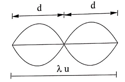
If λu is the wave length of the ultrasonics, then we can write,
eqn (2)

Then, eqn. (1) becomes,
eqn (3)

If ‘f ’ is the frequency of ultrasonic oscillations then the velocity of ultrasonic wave is
eqn (4)

Equation (4) gives the velocity of ultrasonic waves.
| Read More Topics |
| Basic components of a laser |
| Different types of scans |
| Basic concepts of laser |