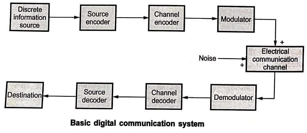

Fig shows the basic elements of a digital communication system. The source and the destination are the two physically separate points. When the signal travels in the communication channel, noise interferes with it. Because of this interference, the smeared or disturbed version of the input signal is received at the receiver. Therefore the signal received may not be correct. That is errors are introduced in the received signal. Thus the effects of disturbance and noise due to the communication channel limit the rate at which signal can be transmitted. The probability of error in the received signal and transmission rate are normally used as performance measures of the digital communication system.
The information source generates the message signal to be transmitted. In case of analog communication, the information source is analog. In case of digital communication, the information source produces a message signal which is not continuously varying with time. Rather the message signal is intermittent with respect to time. The examples of discrete information sources are data from computers, teletype etc. Even the message containing text is also discrete. The analog signal can be transmitted to discrete signal by sampling and quantization. In sampling, the analog signal is chopped off at regular time intervals. Those chopped samples form a discrete signal.
The symbols produced by the information source are given to the source encoder. These symbols cannot be transmitted directly. They are first converted in to digital form (binary sequence of 1’s and 0’s) by the source encoder. Every binary ‘1’ or ‘0’ is called a bit. The group of bits is called a codeword. The source encoder assigns codewords to the symbols. For every distinct symbol there is unique codeword. The codeword can be of 4,8,16 or 32 bits length. As the number of bits are increased in each codeword. The symbols that can be represented are increased.
The communication channel adds noise and interference to the signal being transmitted. Therefore errors are introduced in the binary sequence received at the receiver. Hence errors are also introduced in the symbols generated from these binary codewords. To avoid these errors, channel coding is done. The channel encoder adds some redundant binary bits to the input sequence. These redundant bits are added with some properly defined logic.
In the previous sections we studied why modulators and demodulators are required. Whenever the modulating signal is discrete (binary codewords), then digital modulation techniques are used. The carrier signal used by digital modulators is always continuous sinusoidal wave of high frequency. The digital modulator maps the input binary sequence of 1’s and ‘0’s to analog signal waveforms. If one bit at a time is transmitted, then digital modulator signal is s1(t) to transmit binary ‘0’ and s2(t) to transmit binary ‘1’. For example consider the output of digital modulator shown in Fig.

The signal s1(t) has low frequency compared to signal s2(t). It is Frequency Modulation (FM) in two steps corresponding to binary symbols ‘0’ and ‘1’. Thus even though the modulated signal appears to be continuous, the modulation is discrete (or in steps). Single carrier is converted into two waveforms s1(t) and s2(t) because of digital modulation.
| Read More Topics |
| Basic communication system |
| Modulation and demodulation in communication system |
| Point to point link |
| Operating system components |