COMPONENTS OF AUTOMATIC CONTROL SYSTEM
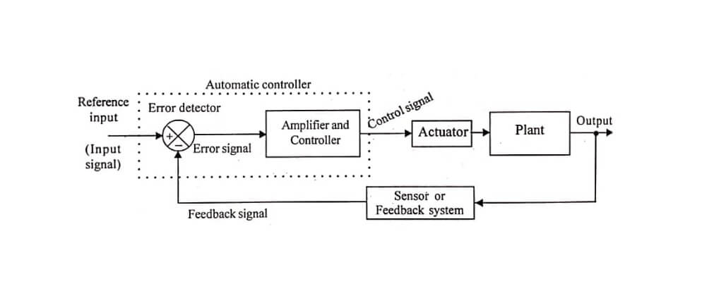
The basic components of an automatic control system are error detector, Amplifier and Controller, Actuator (power actuator), plant and sensor or Feedback system. The block diagram of an automatic control system
The plant is the open loop system whose output is automatically controlled by closed loop system. The combined unit of error detector, amplifier and controller is called automatic controller, because without this unit the system becomes open loop system.
In automatic control systems the reference input will be an input signal proportional to desired output. The feedback signal is a signal proportional to current output of the system. The error detector compares the reference input and feedback signal and if there is a difference it produces an error signal. An amplifier can be used to amplify the error signal and the controller modifies the error signal for better control action.
The actuator amplifies the controller output and converts to the required form of energy that is acceptable for the plant. Depending on the input to the plant, the output will change. This process continues as long as there is a difference between reference input and feedback signal. If the difference is zero, then there is no error signal and the output settles at the desired value.
The function of error detector is to compare the reference input with feedback signal, to produce an error signal if there is a difference between them. The error signal is used to correct the output if there is a deviation from the desired value. Examples of error detector are potentiometer, LVDT (linearly Variable Differential Transformer), Synchros, etc.,.
Generally, the error signal will be a weak signal and so it has to be amplified and then modified for better control action. In most of the system the controller itself amplifies the error signal and integrates or differentiates to produce a control signal (i.e., modified error signal). The different types of controllers are P , PI, PD and PIUD controllers.
The controllers employed may be electrical, electronic, hydraulic or pneumatic depending on the nature of error of signal. if the error signal is electrical then the controller may be electrical or electronic and they are designed using R-C circuit or operational amplifiers. If the error signal is mechanical then the controller, may be hydraulic or pneumatic and they are designed using hydraulic servomotors or pneumatic flapper valves.
The actuator is a power amplifying device that produces the input to the plant according to the control signal. The actuator may be a pneumatic motor/valve, hydraulic motor or electric motor. Examples of electric motors employed as actuator are DC servomotor, AC servomotor and stepper motor.
The feedback system samples the output to produce a feedback signal which is proportional to current output. Also the feedback system should convert the output Variable into another suitable variable such as displacement, pressure or voltage, so that it can be used to compare with the reference input. Usually the feedback system consists of sensor and associated circuit/devices. Transducers, Tachnogenerators, etc., are used as feedback systems.
Many transducers like thermocouples, photo electric cells produce dc voltages proportional to the quantity to be measured. If this signal is to actuate an ac system, then this dc signal has to be converted to an ac signal before it is applied to ac systems. The device which transfers the information available in a dc signal to ac signal is called a modulator and the conversion process is called modulation. In modulation the control signal is superimposed on a high frequency carrier. Certain control system components like ac tachogenerators produces a modulated output signal. Hence the information is obtained by demodulation. The device which is used to extract the information available on a high frequency carrier is called demodulator and the process is called demodulation. In demodulation the control signal is extracted from the carrier signal.
Sometimes power transmitters like transformers, levers and gear trains are employed n control system. The function of transformer is to alter the voltage and current level of the power being transmitted. The function of lever is to alter the force and that of gear train is to alter the torque of the power being transmitted.
POTENTIOMETERS – COMPONENTS CONTROL SYSTEM
A potentiometer is a device that can be used to convert a linear or angular displacement into a voltage. A potentiometer is a variable resistance whose value varies according to the angular/linear displacement of the wiper contact (movable contact)
The resistance element can be constructed by winding resistance wire on a former or by depositing a conducting material on a plastic base. The potentiometer has an input shaft to which a wiper is attached. The displacement is applied to the input shaft. When the shaft moves, the wiper contact slides over the resistance material.
The potentiometer is excited by a dc or ac voltage. The output voltage is measured at wiper contact a
APPLICATION OF POTENTIOMETERS
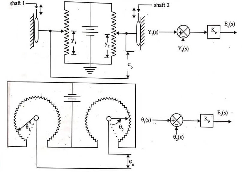
Potentiometer can be used either to convert a mechanical motion to proportional voltage or as an error signal. A single potentiometer excited by dc or ac voltage is used to produce an output voltage proportional to displacement of the input shaft.
When potentiometers are used as error detector, two identical potentiometers are required. Both the potentiometer are excited by the same source and at some potential. Hence, if the wiper arm of both the potentiometer are in the same position then the voltage between two wiper arms is proportional to the difference between the displacement of both the wiper arms.
CHARACTERISTICS OF POTENTIOMETER
- The ideal characteristics of a potentiometer is linear variation of resistance with displacement. This is best realized by having very large radius, more number of turns and high resistance elements.
- The device which measures the output voltage of potentiometer should have high input impedance to avoid loading error. If necessary an isolation amplifier with high input impedance may be used.
- When the wiper slides over resistance it makes simultaneous contact with adjacent turns to avoid discontinuity in output. Consequently the output is in the form of staircase steps.
Hence we defines a term called resolution which specifies the output voltage per step. The resolution of a potentiometer is defined as the ratio of number of steps to total number of turns. The resolution of potentiometer is an important factor in the determination of minimum value of output voltage.
SPECIFICATIONS OF POTENTIOMETER
The specification of potentiometer used in control system are the following,
- Turns per unit length is in the range of 6 to 30 turns per mm.
- Torque required for wiper movement is the range of 1×10⁻³Kg-m to 1×10⁻²Kg-m.
- The total resistance of the potentiometer is in the range of 25 ohms to 1 mega-ohms.
- Power rating is 1 to 10 watts.
- Heat dissipation is 1/2 watts per cm2.
- Excitation voltage is 4 to 20 volts.
- Voltage gradient is 0.01 to 0.05 volt per degree.
AC POTENTIOMETER – CONTROL SYSTEM
In potentiometer excited by ac supply the output will be a modulated voltage. The carrier is the excitation voltage. The envelope of the carrier is modulated by the movement of the wiper arm. Hence, the information is available in the envelope of the carrier. The ac potentiometer will have inductive effect in addition to resistance which leads to difficulty in balancing the potentiometers used as error detectors.
SYNCHROS
The term synchro is a generic name for a family of inductive devices which works on the principle of a rotating transformer (Induction motor). The trade names for synchros are Selsyn, Autosyn and Telesyn. Basically they are electro-mechanical devices or electromagnetic transducers which produces an output voltage depending upon angular position of the rotor.
A synchro system is formed by interconnection of the devices called the synchro transmitter and the synchro control transformer. They are also called Synchro pair. The synchro pair measures and compares two angular displacements and its output voltage is approximately linear with angular differences of the axis of both the shafts. They can be used in the following two ways,
- To control the angular position of load from a remote place/long distance.
- For automatic correction of changes due to disturbance in the angular position of the load.
SYNCHRO TRANSMITTER
Construction
The constructional features, electrical circuit and a schematic symbol of synchro transmitter. The two major parts of synchro transmitter are stator and rotor. The stator is identical to the stator of three phase alternator. It is made of laminated silicon steel and slotted on the inner periphery to accommodate a balanced three phase winding. The stator winding is concentric type with the axis of three coils 1200 apart. The stator winding is star connected (Y-connection).
The rotor is of dumb bell construction with a single winding. The ends of rotor winding are terminated on two slip rings. A single phase ac excitation voltage is applied to rotor through slip rings.
Working principle – Components of Control System
When the rotor is excited by ac voltage, the rotor current flows, and a magnetic field is produced. The rotor magnetic field induces an emf in the stator coils by transformer action. The effective voltage induced in any stator coil depends upon the angular position of the coils axis with respect to rotor axis.
STEPPER MOTORS
A stepper motor transforms electrical pulses into equal increment of rotary shaft motion called steps. Components of Control System A one-to-one correspondence exists between the electrical pulses and the motor steps. They control windings of the stepper motor with a frequency and sequence corresponding to the command issued. It has a wound stator and a non excited rotor. They are classified as variable reluctance, permanent magnet or hybrid, depending on the type of rotor. They are also classified as 2-phase, 3-phase or 4-phase depending on the number of windings (called control winding) on the stator.
The number of teeth or poles on the rotor and the number of poles on the stator determine the size of the step (called the step angle). The step angle is equal to 3600 divided by the number of steps per revolution. Motors are available with step rates of 200 steps per revolution. Further increase in step rate is limited by mechanical and physical constraints. This limitation has been overcome by electronic methods of reducing the step size. Half-stepping and microstepping are techniques of electronically dividing each step into two half steps or from 10 to 125 microsteps.
A single pulse advances the shaft position by one angular step and a train of pulses produces a rotation in rapid steps, each with a non cumulative error of say ±3%. For example, with a step angle of 1.80, one pulse will move the rotor position by 1.80±0.050, a train of 1000 pulses will give a rotation angle of 18000±0.050 equivalent to five complete revolutions. With such an accuracy, a stepper motor does not require closed loop control, since positional precision is determined by the number of pulses.
A single pulse develops a detent torque which turns the rotor by one angular step and it comes to rest after a short damped oscillations which depends upon the system inertia, elastically and damping. A properly timed pulse sequence sustains a slewing rotation, the rotor passing through a corresponding number of angular steps and develops an effective mean torque and speed (or acceleration) all with positional accuracy.
APPLICATIONS OF STEPPER MOTOR
Stepper motors are used in computer peripherals, X-Y plotters, scientific instruments, robots and machine tools. Stepper motors are used in quartz-crystal watches. The one used in wrist watch has a diameter of 3mm and takes a few microamperes at 1.5V. Stepper motors are also used for colour registration in printing. Stepper motors can upgrade mechanical systems by replacing cams, complex linkages, and similar mechanisms to give greater precision and production rate. Stepper motors are available with torques in precision and production rate. Stepper motors are available with torques in the range from 0.5µN-m to 100N-m, outputs in the range from millwatts to several kilowatts and pulse rates of 1200 or more per second.
ACTIVE ROTOR OR PERMANENT MAGNET ROTOR STEPPER MOTOR
The stator of this type of stepper motor has salient poles carrying control windings. Each pole carries a control winding. A pair of control winding are connected in series and called a phase, Components of Control System.
Stepper motors may be wound for any number of phases, most popularly being two, three and four-phase stepper motors. The rotor is made in the form of a permanent magnet spider cast integral or assembled of a number of permanent magnets.
On taking Laplace transform of equation (2.93) we get, E(s)= Kt s θ(s)t
The equation is the transfer function of DC tachogenerator. A problem associate with dc arranged in space quadrature, (the windings are fixed on the inner periphery of the stator such that the angle between their axes is 900) and the squirrel cage rotor. One stator winding is called reference winding and it is excited by a sinusoidal voltage of frequency, ω0. The other winding is called output winding, in which an emf is induced when the rotor rotates. The schematic diagram of ac tachogenerator is .
When the rotor is stationary, no emf is induced in the output winding and therefore the output winding voltage is zero. When the rotor starts rotating, a voltage at the reference frequency, ωc is induced in the output winding. The magnitude of the winding output voltage is proportional to the rotational speed.
A change in the direction of shaft rotation causes a 1800 phase shift in the output winding voltage. When the output winding voltage is in phase with reference, the direction of rotation is said to be positive and when the output winding voltage is 1800 out of phase, the direction is said to be negative. The output winding voltage of an ac tachogenerator is thus in modulated form.
If the reference winding voltage, et(t) = Etsinωct
Then the output winding voltage, em(t) = e(t) sinωct
The output winding voltage, em(t) of the tachogenerator is demodulated to get output voltage e(t), because the information about shaft speed is available on the envelope of em(t). After demodulation, the output voltage of ac tachogenerator is same as that of dc tachogenerator.
Output voltage, e(t) α dθ/dt; e(t) = Kt
Where, kt=sensitivity of tachogenerator, volts/(rad/sec).
On taking Laplace transform of equation (2.95) we get, E(s)= Ktsθ(s)
The equation Components of Control System is the transfer function of ac tachogenerator.
