Michelson Interferometer
Construction:
It consists of a monochromatic light source, a beam splitter and two mirrors. The basic principle involved in Michelson interferometer is constructive and destructive interference when one mirror remains fixed and the other is moved.
The above fig shows the working of Michelson interferometer. A monochromatic light from an extended source falls on a beam splitter which splits the rays into two equal rays of same intensity at right angles.
In two rays, one ray is transmitted to mirror M1 and other one is reflected through beam splitter to mirror M2. The rays are reflected back from both the mirror M1 and M2 reunited at the semi-reflecting surface. Then, it is transmitted to the eye. Mirror M1 is movable and mirror M2 is fixed. The ray reflected from M1 serves as reference beam. Both the mirrors are at the same distance from beam splitter, the observer will see bright spot due to constructive interference.
If the movable mirror M1 is shifted by quarter wavelength, then the beam will be returned to observer 180° out of phase and darkness will be observed because of destructive interference.
Each half wavelength of mirror travel produces a change in the measured optical path of one wavelength and 360° phase change will occur from the moving mirror reflected beam.
The compensator plate is used in each of the path of mirror M. so that exactly the same amount of glass is introduced in each of the path.
If the reflected beam from the fixed mirror and the reflected beam from the moving mirror rejoin at the beam splitter, they alternatively reinforce and cancel each other as the mirror moves.
The conditions for improving Michelson interferometer are,
- Use of laser light source for measuring longer distances.
- Instead of using mirror the cube corner reflector is suited best suitable for reflecting the light.
- Photocells can be employed to convert light intensity variation in voltage pulses to given direction of position change.
Dual Frequency Laser Interferometer
It is used to measure displacement, high precision measurement of lengths, Angles, speeds and refractive indices as well as derived static and dynamic quantities.
Construction:
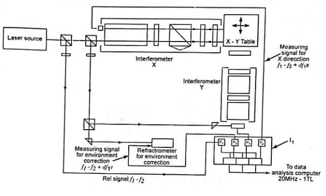
Two frequencies f1 and f2 are generated in a laser tube such that ƒ1 – ƒ2 = 640MHz. The frequency stability of He – Ne laser is responsible for outstanding performance of the interferometer. The laser beam is splitted into reference beam and measuring beam by the beam splitter. The measuring beam is directed to a movable measuring mirror and stationary. Reference mirror is reflected on the photocell The photo detector – 1 is used for detecting the reference signal.
The two frequencies in the measuring beam being separated by beam splitter so that the measuring mirror receives light of frequency ƒ1 only. But, the light strikes the reference consisting of only ƒ2. The frequency difference ƒ1 – ƒ2 = 640 MHz is measured by detector 2 when mirror is at rest.
Working:
The laser source generates two frequencies ƒ1 and ƒ2. The reference signal ƒ1 – ƒ2 is detected in the photo detector P2. The measuring signals ƒ1 – ƒ2 ± Δƒ1 (x) for x direction measurement and measuring signal of ƒ1 – ƒ2 ± Δƒ1 (y) are sensed by photo detectors P3 and P4. The environment correction is made by the photo detector P1. In the dual frequency laser interferometer, there are two interferometers used for x and y directions.
Applications:
- It is used for both incremental displacement and angle measurements.
- The resolution 2nM in 10M measuring range.
Twyman Green Interferometer
The Twyman Green interferometer is used as a polarizing interferometer with variable amplitude balancing between sample and reference waves. For an exact measurement of the test surface, the instrument error can be determined by an absolute measurement. This error is compensated by storing the same in microprocessor system and subtracting from the measurement of the test surface.
It has the following advantages
- It permits testing of surface with wide varying reflectivity.
- It avoids undesirable feed back of light reflected of the tested surface and the instrument optics.
- It enables utilization of the maximum available energy.
- Polarisation permits phase variation to be effected with the necessary precision.
Laser Interferometer Applications
Linear measurement
In linear measurements, the beam existing from the laser head is splitted up at the surface of a polarizing beam splitters as shown in fig.

In the splitted two frequencies, one frequency is reflected to the reference cube corner and the other beam is transmitted to the measuring retro reflector.
Both frequencies are reflected back along a common axis to the photo detector block. In the two frequencies, one includes a Doppler frequency shift whenever the measured retro reflector moves.
Angular measurement
In angular measurements, a 45° mirror is mounted in place of the reference retro reflector so that the two frequencies ƒ1 and ƒ2 are sent out parallel as shown in fig.

The angular displacement of the retro reflector mount causes a differential Doppler shift in the returned frequencies which is not done by axial displacement.
It is positive to measure angle up to 10 ± 10° with a resolution of 0.1 second with laser interferometer. The change in the path difference of the reflected beam represents the side of the triangle opposite to the angle being measured.
| Read More Topics |
| Definition of metrology |
| 8086 Microprocessor intel |
| Straightness measurement |
| Measurement of screw threads |


