Before discussing the gyroscopic effect on naval ships, first let us brief the terminology used in connection with the naval ship.
Ship Terminology
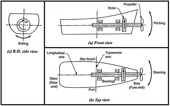
The front, top, and side views of a naval ship are shown in fig (a), (b) and (c) respectively.

The terms used are:
- Bow: It is the fore or front end of the ship.
- Stern or aft: It is the rear end of the ship.
- Port: It is the left hand side of the ship when looking from the rear end.
- Star board: It is the right hand side of the ship when looking from the rear end.
Types of Movements
A sea ship may have the following three movements:
- Steering: It is the turning of a ship in a curve either to the right or to the left hand side while the ship moves forward.
- Pitching: It is the upward or downward angular movement of the ship in a vertical plane, about its transverse axis, from the horizontal position.
- Rolling: It is the sideway motion of the ship about its longitudinal axis.
Now we shall discuss the gyroscopic effect in a ship during steering, pitching, and rolling.
Steering is nothing but turning in a curve while the ship moves forward. During steering (left or right turn) of a ship, the rotor and propeller of the ship (which is spinning about its own axis) precess (changes the axis of spin).
Due to this precession of the spin axis, the reactive gyroscopic couple is applied by the rotor shaft on the ship.
It may be noted that effect of gyroscopic couple on a ship during steering is very much similar to that of an aeroplane taking turn to the left or right hand side.
Thus the gyroscopic effect on the ship during steering may be obtained in the similar way as for aeroplane.
However, for better understanding, the same procedure is repeated for the ship, as below.
Gyroscopic Effect During Steering when Rotor/Propeller Rotates in Clockwise Direction and Ship Steers Left when seen from the Stern
Let the rotor/propeller rotates in clockwise direction when seen from the stern and the ship steers left, as shown in Fig.
Illustrates diagrammatically the direction of reactive couple and its effect on the body of the ship, when rotor/propeller rotates in clockwise and aeroplane takes left turn, when seen from the stern.
For simplicity, the Fig is split into four figures as shown in fig. Fig (a) shows the vector diagram, Fig (b) the axis diagram, Fig (c) the plane diagram, and Fig (d) depicts the gyroscopic effect.
Procedure to Determine the Direction of Gyroscopic Couple
Step 1: Locate direction of spin vector
Curl the fingers of the right hand along the direction of rotation of rotor/propeller (in this case, along clockwise direction), then the direction of thumb indicates the spin vector.
Step 2: Obtain direction of active gyroscopic couple vector
Since the ship steers to the left, therefore by turning the spin vector through 90° in the direction of precession, we get the direction of active gyroscopic couple vector.
Step 3: Find direction of reactive gyroscopic couple vector
As we know, the direction of reactive gyroscopic couple vector is opposite to the direction of active gyroscopic couple vector, as shown in fig.
Step 4: Observe direction of reactive gyroscopic couple
Point the thumb of the right hand in the direction of reactive gyroscopic couple vector, then the curling fingers give the direction of reactive gyroscopic couple.
Gyroscopic Effect
As could be seen from fig. The effect of the reactive gyroscopic couple is to raise the bow and depress the stern.
| Read More Topics |
| Precessional angular motion |
| Radial spring governor |
| Centrifugal governors |
[sc_fs_faq html=”true” headline=”h2″ img=”” question=”What is gyroscopic torque?” img_alt=”” css_class=””] Whenever a rotating body changes its axis of rotation, a torque is applied on the rotating body. This torque is known as gyroscopic torque. [/sc_fs_faq]


