Laser Doppler Anemometer enables the measurement of instantaneous velocity of a gas or a liquid flowing in a glass walled channel. It offers the non-disturbance advantages of optical methods while affording a very precise quantitative measurement of local flow velocity. This instrument is the most recent advancement in the area of flow measurement especially measurement of high frequency turbulence fluctuations.
The theory of Laser Doppler Anemometer (LDA) is based on the principle of Doppler shift. It involves the focusing of laser beams at the point where the velocity is to be measured and then sensing with a photo detector the light scattered by thin particles carried along with the fluid as it passes through the laser focal point. The velocity of particles which is assumed to be equal to the fluid velocity causes a Doppler shift of the frequency of the scattered light a and produces a photo detector signal related to the velocity.
It is not necessary to insert artificial tracer particles always to function this instrument because normally microscopic particles are present in liquids may be sufficient. However, it may become essential to insert artificial particles from outside in case of gases. It is obvious that the Laser Doppler Anemometer measures the velocity of scattering particles. Under extreme conditions, particles may not perfectly follow the flow and therefore there may be errors in measurement of flow velocity. By providing smaller particles, almost accurate indication of fluid velocity may be obtained as the slip velocity between particles and fluid will be small.
There are two distinct approaches in vogue to explain the working of an LDA. These are:
- Reference beam mode, and
- Interference fringe mode.
Reference beam mode
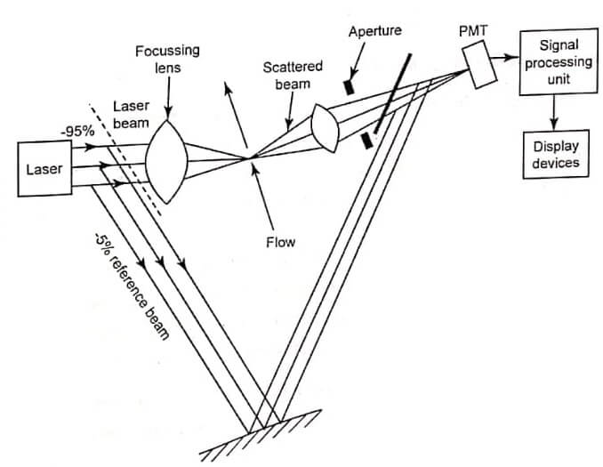
In this mode, laser light is split into two beams which are directed at the point of measurement in the field at an angle θ. The light scattered in the direction of reference beam is picked up and photo-mixed in the Photo-Multiplier Tube (PMT) with the reference beam propagating in the same direction as shown in fig.
The photo multiplier tube yields a signal at the Doppler frequency. The reference beam need not traverse through the same volume but it can be added to the scattered beam at PMT. The reference beam strength is considerably smaller than that of the other beam so that scattered beam is relatively stronger and a good heterodyne signal from PMT is obtained.
This mode of operation can be used with advantages when the suspension density is fairly high. Further, the alignment tolerance required for the heterodyne process is not so critical. Thus, this mode of operation is relatively easy to use.
Interference fringe mode
Working principle of the interference fringe mode gives a better insight of the appearance of Doppler signal. Fig. shows the diagram of fringe mode anemometer. In this anemometer, the laser beam is split into two equal intensity such as parallel beams with the help of two coated optical flat (called beam splitter). A lens focuses the beams at a point where the velocity of flow fluid is to be measured. The scattered beam of light moving through the fringe pattern is selectively collected by a combination of lens and the hole aperture. It is then detected by a PMT. The light intensity verses time is displayed on a display device.
In both the cases, the laser source employed is usually helium-neon (He-Ne) gas laser although argon ion lasers provide a more intense beam output.

Advantages
- It measures only the velocity.
- Volume of sensing part is very small.
- There is no addition of physical object to avoid disturbances.
- It has very high accuracy.
- It has a high frequency response.
- It is used to measure both the flow of liquids and gases.
Disadvantages
- It involves the use of transparent channels.
- There is no using of tracer particles to divert the light beam.
- Cost is high and it has a high degree of complexity.
Applications
- For investigating the boundary layers and shock wave interaction.
- For determining the 3-D wing tip vortices near tips of wings of aircrafts.
- For measuring the flow between blades of a turbine.
- Combustion and flame phenomena in gas turbines.
- Jet propulsion systems.
- For measuring the blood flows.
- In remote sensing of wind velocities.
- See More : Float technique for other flow
- See More : Capsule pressure sensor
- See More : Diaphragm pressure sensors