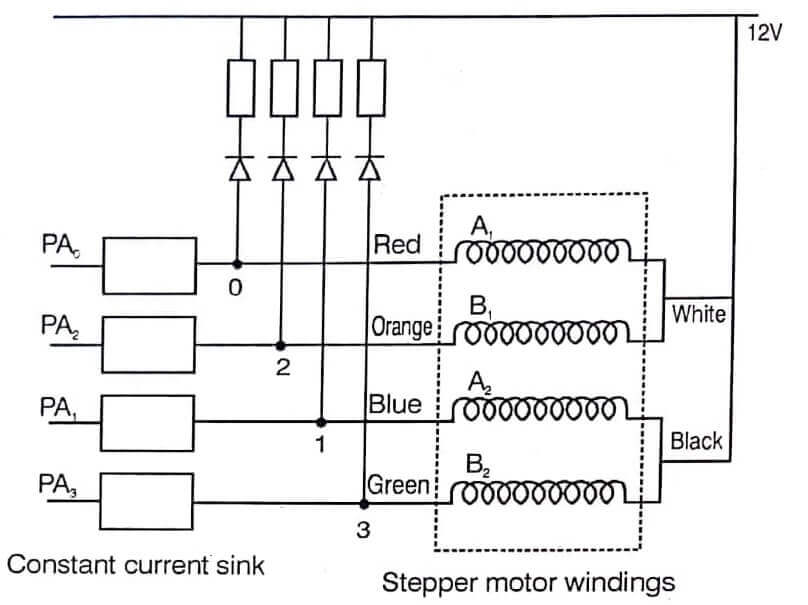
A stepper motor control is a specially constructed DC motor. It has 4 windings arranged such that instead of running in the usual continuous fashion the motor rotates in precise steps, from one fixed position to another. The common step sizes range from 0.9 to 30 degrees.
The stepping action is achieved by proper combination of fields. Fig the schematic of the stepper motor windings. Table shows the pulsing sequence of windings when bit D0 is in 0 level the coil A 1 is energised, and so on. Changing the excitation from A1 & A2 to A2 & B1 causes the shaft to rotate by one step clockwise. Each successive line of the table causes one step. Reversing the order in the sequence table causes the shaft to rotate counter clockwise. Thus the shaft can be given precise angular rotations.
| Clock Wise | B2 | B1 | A2 | A1 | Anti Clock Wise |
| D3 | D2 | D1 | D0 | ||
| ↓ | 1 | 1 | 0 | 0 | ↑ |
| 1 | 0 | 0 | 1 | ||
| 0 | 0 | 1 | 1 | ||
| 0 | 1 | 1 | 0 | ||
| 1 | 1 | 0 | 0 |
Such motors can be used to provide precise movements as in robot arms, flooppy drives, print head movement and paper rotation in computer printers, machine tool control etc. In all these and many other applications stepper motors are used.

The coils require 1 Amp current for rotation, at 12V. The 12V power supply should be capable of supplying more current. Transistor circuits are used as driver stages as given in fig. The PNP transistor T1 is ON when D3 bit is 0 it is OFF when D3 bit is 1. T2 is ON when T1 is ON, it is OFF when T1 is OFF. When T2 conducts, there is a current through the coil B2. From this it is clear than when D3 bit is zero, coil B2 is energised.
Similarly there are pairs of transistor circuits to energise the coils A1, A2, and B1 as shown in the table.
Zero level in D0 bit energises coil A1
Zero level in D1 bit energies coil A2
Zero level in D2 bit energises coil B1
Zero level in D3 bit energises coil B2
The pulsing of these stages can be done with the program given. From Table it can be found that the starting word 1100 is essentially shifted left one bit in each step of the sequence. The PPI chip 8255 on the kit can be used for the purpose of interfacing.
The program starts with the word 1100 and outputs it through one of the ports. It shifts the word left and outputs it through the same port for each step of rotation of the shaft. For Anti-clock wise rotation, the word is shifted right. The number of steps required and the direction of rotation (D0 =0 for clock wise, 1 for anti-clockwise) are loaded in registers.
| Read More Topics |
| Features of Microcontroller |
| Data Manipulation |
| Instruction set architecture of 8051 |
| Microprocessor controlled temperature system |
| Communication between 8086 and 8089 |


