The network layer is designed as a packet switched network. This means that the packet at the source is divided into manageable packets, normally called datagrams. Individual datagrams are then transferred from the source to the destination.
The received datagrams are assembled at the destination before recreating the original message. The packet-switched network layer of the Internet was originally designed as a connectionless service, but recently there is a tendency to change this to a connection oriented service. We first discuss the dominant trend and then briefly discuss the new one.
Connectionless Service
When the Internet started, the network layer was designed to provide a connectionless service, in which the network layer protocol treats each packet independently, with each packet having no relationship to any other packet. The packets in a message may or may not travel the same path to their destination.
When the Internet started, it was decided to make the network layer a connectionless service to make it simple. The idea was that the network layer is only responsible for delivery of packets from the source to the destination.
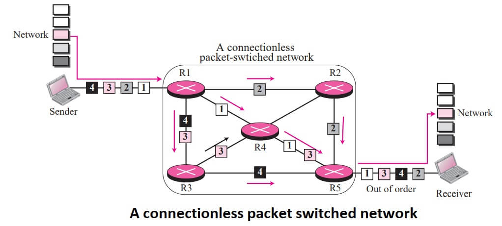
When the network layer provides a connectionless service, each packet traveling in the Internet is an independent entity; there is no relationship between packets belonging to the same message. The switches in this type of network are called routers.
A packet belonging to a message may be followed by a packet belonging to the same message or a different message. A packet may be followed by a packet coming from the same or from a different source.
Each packet is routed based on the information contained in its header: source and destination address. The destination address defines where it should go; the source address defines where it comes from. The router in this case routes the packet based only on the destination address.
The source address may be used to send an error message to the source if the packet is discarded. Figure shows the forwarding process in a router in this case. We have used symbolic addresses such as A and B.
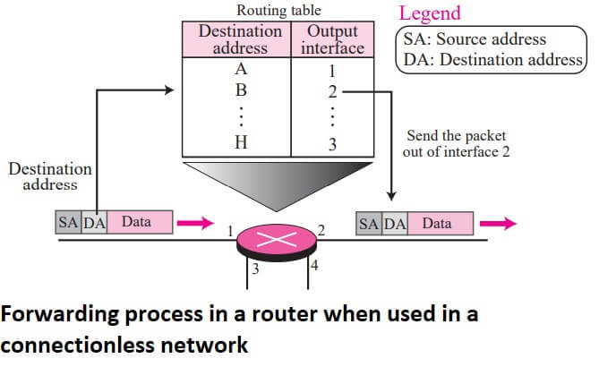
In a connectionless packet-switched network, the forwarding decision is based on the destination address of the packet.
Delay In Connectionless Network
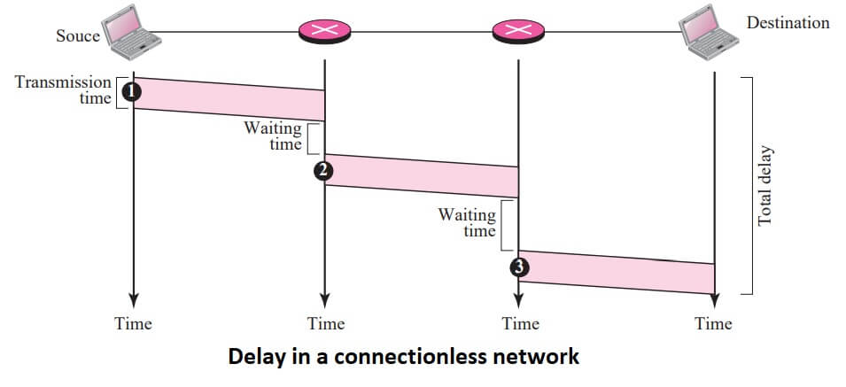
If we ignore the fact that the packet may be lost and resent and also the fact that the destination may be needed to wait to receive all packets, we can model the delay as shown in Figure.
Connection-Oriented Service
In a connection-oriented service, there is a relation between all packets belonging to a message. Before all datagrams in a message can be sent, a virtual connection should be set up to define the path for the datagrams. After connection setup, the datagrams can follow the same path. In this type of service, not only must the packet contain the source and destination addresses, it must also contain a flow label, a virtual circuit identifier that defines the virtual path the packet should follow.
We will shortly show how this flow label is determined, but for the moment, we assume that the packet carries this label. Although it looks as though the use of the label may make the source and destination addresses useless, the parts of the Internet that use connectionless service at the network layer still keep these addresses for several reasons.
One reason is that part of the packet path may still be using the connectionless service. Another reason is that the protocol at the network layer is designed with these addresses and it may take a while before they can be changed. Figure shows the concept of connection-oriented service.
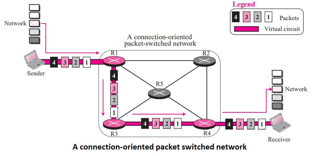
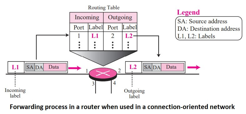
Each packet is forwarded based on the label in the packet. To follow the idea of connection-oriented design to be used in the Internet, we assume that the packet has a label when it reaches the router.
In this case, the forwarding decision is based on the value of the label, or virtual circuit identifier as it is sometimes called.
To create a connection-oriented service, a three-phase process is used: setup, data transfer, and teardown. In the setup phase, the source and destination addresses of the sender and receiver is used to make table entries for the connection-oriented service.
In the teardown phase, the source and destination inform the router to delete the corresponding entries. Data transfer occurs between these two phases.
In a connection-oriented packet switched network, the forwarding decision is based on the label of the packet.
Setup Phase
In the setup phase, a router creates an entry for a virtual circuit. For example, suppose source A needs to create a virtual circuit to destination B. Two auxiliary packets need to be exchanged between the sender and the receiver: the request packet and the acknowledgment packet.
Request packet A request packet is sent from the source to the destination. This auxiliary packet carries the source and destination addresses.
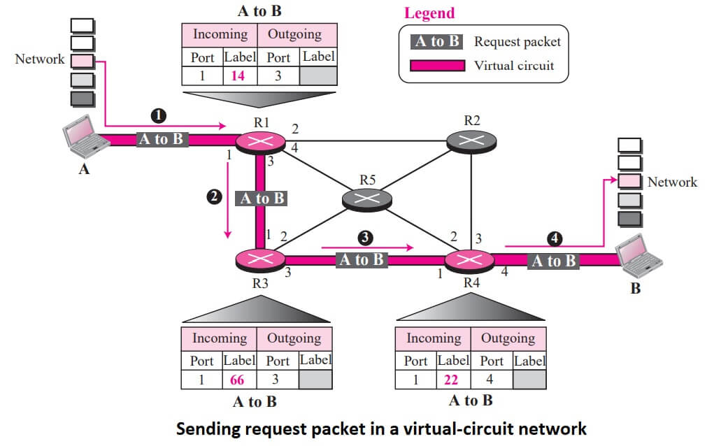
- Source A sends a request packet to router R1.
- Router R1 receives the request packet. It knows that a packet going from A to B goes out through port 3. How the router has obtained this information is a point covered in future chapters. For the moment, assume that it knows the output port. The router creates an entry in its table for this virtual circuit, but it is only able to fill three of the four columns. The router assigns the incoming port (1) and chooses an available incoming label (14) and the outgoing port (3). It does not yet know the outgoing label, which will be found during the acknowledgment step. The router then forwards the packet through port 3 to router R3.
- Router R3 receives the setup request packet. The same events happen here as at router R1; three columns of the table are completed: in this case, incoming port (1), incoming label (66), and outgoing port (2).
- Router R4 receives the setup request packet. Again, three columns are completed: incoming port (2), incoming label (22), and outgoing port (3).
- Destination B receives the setup packet, and if it is ready to receive packets from A, it assigns a label to the incoming packets that come from A, in this case 77. This label lets the destination know that the packets come from A, and not other sources.
Acknowledgment Packet A special packet, called the acknowledgment packet, completes the entries in the switching tables.
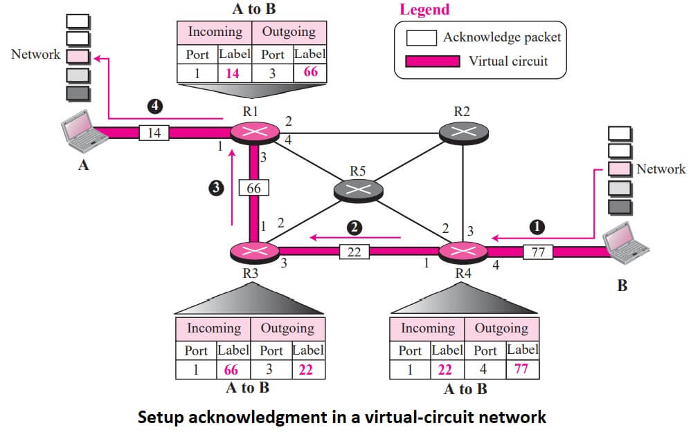
The destination sends an acknowledgment to router R4. The acknowledgment carries the global source and destination addresses so the router knows which entry in the table is to be completed. The packet also carries label 77, chosen by the destination as the incoming label for packets from A. Router R4 uses this label to complete the outgoing label column for this entry. Note that 77 is the incoming label for destination B, but the outgoing label for router R4.
Router R4 sends an acknowledgment to router R3 that contains its incoming label in the table, chosen in the setup phase. Router R3 uses this as the outgoing label in the table.
Router R3 sends an acknowledgment to router R1 that contains its incoming label in the table, chosen in the setup phase. Router R1 uses this as the outgoing label in the table.
Finally router R1 sends an acknowledgment to source A that contains its incoming label in the table, chosen in the setup phase.
The source uses this as the outgoing label for the data packets to be sent to destination B.
Data Transfer Phase
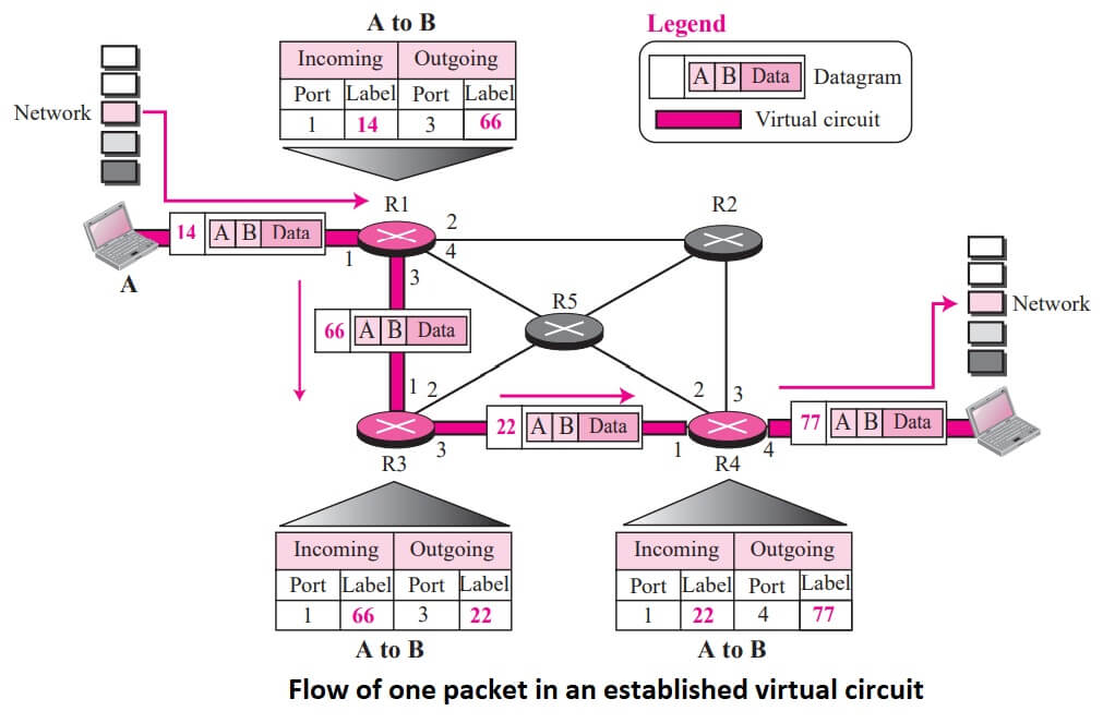
The second phase is called the data transfer phase. After all routers have created their routing table for a specific virtual circuit, then the network-layer packets belonging to one message can be sent one after another.
we show the flow of one single packet, but the process is the same for 1, 2, or 100 packets. The source computer uses the label 14, which it has received from router R1 in the setup phase.
Router R1 forwards the packet to router R3, but changes the label to 66. Router R3 forwards the packet to router R4, but changes the label to 22. Finally, router R4 delivers the packet to its final destination with the label 77. All the packets in the message follow the same sequence of labels to reach their destination. The packet arrives in order at the destination.
Teardown Phase
In the teardown phase, source A, after sending all packets to B, sends a special packet called a teardown packet. Destination B responds with a confirmation packet. All routers delete the corresponding entry from their tables.
Delay In Connection-Oriented Network
If we ignore the fact that the packet may be lost and resent, we can model the delay as shown in figure.

| Read More Topics |
| Wireless LANs |
| Functions of Layer in the OSI Model |
| Glossary for Computer Network |
| ALOHA in Computer Network |
