The pelton wheel is a tangential flow impulse turbine and now in common use. Leston A Pelton, an American engineer during 1880, developed this turbine.
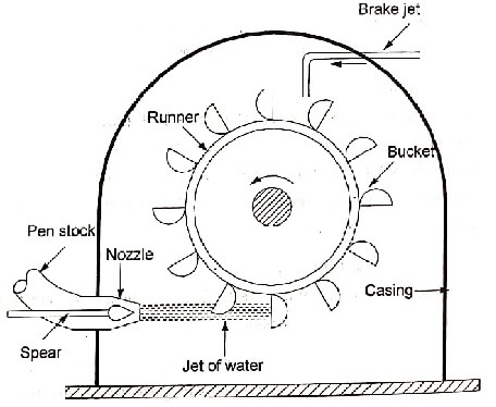
Fig shows the schematic arrangement of a pelton wheel. Pelton wheel consists of the following main parts.
- Penstock
- Spear and nozzle
- Runner with buckets
- Brake nozzle
- Outer casing
- Governing mechanism
Penstock
It is a large sized pipe which conveys water from the high level reservoir to the turbine. Depending upon low head or high head installation, a penstock may be made of wood, concrete or steel. For the regulation of water flow, the penstock is provided with control valves.
Spear and nozzle

At the downstream end of the penstock, it is fitted with an efficient nozzle which converts the whole hydraulic energy into, kinetic energy. Thus the nozzle delivers high-speed jet. To regulate the water flow
through the nozzle and to obtain a good jet of water, a spear is arranged as shown in fig. The spear can move forward or backward thereby decreasing or increasing the annular area of the nozzle flow passage.
Runner with buckets
The runner consists of a circular disc with a number of buckets evenly spaced round its periphery. The runner is mounted on a horizontal shaft supported in small thrust bearings. The buckets have a shape of double semi-elliptical ridge known as splitter. The buckets are either cast internally with the disc or fastened separately. The buckets are so shaped that the angle at the outlet tip varies from 10° to 20° so that the jet of water gets deflected through 160° to 170°. The jet of water impinges on the splitter which divides the jet into two equal portions. After flowing around the smooth inner surface of the bucket, water leaves at its outer edge. The advantage of having hemispherical double cup bucket is that the bearings supporting the Pelton wheel shaft are not subjected to any axial or end thrust.
Outer casing
A casing is made of cast iron or fabricated steel plates. It has no hydraulic function to perform. It is used to prevent the splacing of water and discharge water to tailrace. It also acts as a safeguard against accidents.
Brake nozzle
When the nozzle is closed by moving the spear in forward direction, the amount of water striking on the buckets is reduced to zero. But the runner will revolve for long time due to inertia. To stop the runner in a short time, a small nozzle is provided which directs a jet of water on the back of the buckets. This jet of water is called braking jet.
Governing mechanism
Governing mechanism is used to regulate the water flow to the turbine at constant level so that the speed of the turbine is kept constant. This automatically regulates the quantity of water flowing through the runner in accordance with any variation of load.
Francis Turbine

Francis turbine is an inward flow reaction turbine. It is developed by the American engineer James B. Francis. In earlier stages, Francis turbine had a purely radial flow runner. But, the modern Francis turbine is a mixed flow reaction turbine in which the water enters the runner radially at its outer. periphery and leaves axially at its centre. This arrangement provides a larger discharge area with the prescribed diameter of the runner.
Penstock
It is a large sized conduit which conveys water from the upstream of the dam to the turbine runner. Penstock required for a Francis turbine is larger than that of pelton wheel.
Scroll or Spiral casing
The water from the penstock enters a scroll casing which completely surrounds, the runner. The cross-sectional area of the scroll casing decreases along the flow direction and the area is maximum at inlet and nearly zero at exit. The purpose of casing is to provide an even distribution of water around the circumference of the turbine runner maintaining the constant velocity approximately for the water so distributed. The casing is made of cast steel, plate steel, concrete depending upon the pressure/head to which it is subjected.
Speed ring or stay ring
From scroll casing the water passes through a speed a ring or stay ring. This consists of an upper and a lower ring held together by series of fixed vanes called stay vanes. The number of stay vanes is usually taken as half the number of guide vanes. The function of stay vane is to direct the water from the scroll casing to the guide vanes and also it resists the load imposed upon it. It may be made of cast iron or cast steel.
Guide vanes or Wicket gates
From the speed ring, the water passes through a series of guide vanes or wicket gates. Thus, gates are provided all around the periphery of the turbine runner. The guide vanes direct the water onto the runner at an appropriate angle as per design. Also, it is used to regulate the quantity of water supplied to the runner. The guide vanes are airfoil shaped and they may be made of cast steel, stainless steel or plate steel.
The guide vanes are operated either by means of a wheel or automatically by a governor.
Runner and runner blades
It is a circular wheel on which a series of radial curved vanes are fixed. The vanes are so shaped that water enters the runner radially at outer periphery and leaves it axially at the inner periphery. The runners are made of cast steel, cast iron or stainless steel. They are keyed to the shaft. The driving force on the runner is both due to impulse (deviation in the direction of flow) and reaction (change in pressure and velocity energy) effects. The number of runner blades usually varies from 16 to 24.
Draft tube
After passing through the runner, the water is discharged to the tailrace through a gradually expanding tube called draft tube. Therefore simply; a draft tube is a pipe or passage of gradually increasing cross- sectional area which connects the runner exit to the tailrace.
Propeller Turbine
The propeller turbine is an axial flow reaction turbine which is mainly suitable for low head (upto 30 m) and high flow rate installations such as barrages in rivers. The hub and vanes assembly of this turbine is like a propeller of a ship operating in reverse. The propeller of the ship rotates and thrusts water away behind it and thus produces a momentum to move the ship forward. But in propeller turbine, water flows through the propeller which in turn produces mechanical work.

The water enters the runner in axial direction and during the process of energy transfer, it travels across the blade passage in axial direction and leaves axially. This purely axial flow arrangement provides the largest flow area. The flow velocities are not too large even at larger flow rates. The pressure at the inlet of the blades is larger than the pressure at the exit of the blades. The energy transfer is due to the effect of reaction, i.e. the change in the magnitude of relative velocity across the blades.
| Read More Topics |
| Hydraulics system and model |
| High energy rate forming process |
| Control system in mechatronics |
| Directional control valves |