Potentiometer displacement sensor is a primary sensor which converts the linear motion or the angular motion of a shat into changes in resistance. It is a type of resistive displacement sensor. Linear potentiometers are sensors that produce a resistance output proportional to the linear displacement or position.
Linear potentiometers are essentially variable resistors whose resistance is varied by the movement of a slide over a resistance element.
Rotary potentiometer are sensors that produce resistance output proportional to the angular displacement or position. They can be either wire wound or conductive plastic, and either rectangular or cylindrical.

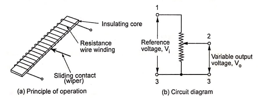
Illustrates the basic principle of a linear potentiometer. The linear potentiometer employs an electrically conductive linear slide member (also called wiper) connected to a variable wire wound resistor (winding) that changes resistance to be equated to the linear position of the device that is monitored.
As the sliding contact moves along the winding, the resistance changes in linear relationship with the distance from one end of the potentiometer.
To measure displacement, a potentiometer is typically wired as a ‘voltage divider’ so that the output voltage is proportional to the distance traveled by the wiper. A known voltage is applied to the resistor ends.
The contact is attached to the moving object of interest. The output voltage at the contact is proportional to the displacement.
The resolution is defined by the number of turns per unit distance, and loading effects of the voltage divider circuit should be considered.
A rotary potentiometer employs a rotary slide member connected to a variable wire wound resistor that changes resistance to be equated to the angular position of the device that is monitored.
Other principles of operations are same as that of linear potentiometer.
The potentiometer can be used as a voltage divider to obtain a manually adjustable output voltage at the slider (wiper) from a fixed input voltage applied across the two ends of the resistance wire winding.
A potentiometer circuit with a resistive load and circuit with equivalent fixed resistors respectively. The voltage across RL can be calculated by: Potentiometer Displacement Sensors
VL=(R2RL)R1RL+R2RL+R3RL) × VS
If RL is large compared to the other resistances (like the input to an operational amplifier), the output voltage can be approximated by the simpler equation.
vL=R2R1+R2×VS
As an example, assume
Vs = 12V, R1 = 1k𝜴 , R2 = 3k𝜴, and RL = 200k𝜴.
Since the load resistance is large compared to the other resistance, the output voltage VL will be approximately,
VL=31+3×12=9V
Due to the load resistance, however, it will actually be slightly lower: ≈8.966V.
One of the most common uses for modern low power potentiometer sensor is as audio control devices. Both sliding pots (also known as faders) and rotary potentiometers (commonly called knobs) are regularly used to adjust loudness, frequency attenuation and other characteristics of audio signals.
The following factors to be considered while selecting the potentiometers:
- Operating temperature
- Shock and vibration
- Humidity
- Contamination and seals
- Life cycle
- Dither
Advantages and Disadvantages of Potentiometers
Advantages:
- Easy to use
- Low cost
- High-amplitude output signal
- Proven technology
- Rugged construction
- Very high electrical efficiency
- Availability in different forms, ranges and sizes
Disadvantages
♦Limited bang width
♦Frictional loading
♦Inertial loading
♦Limited life due to wear
| Read More Topics |
| Tire Pressure Sensor Work |
| Photoelectric sensor working |
| Performance terminology of sensor |
| Central Processing Unit (CPU) |


