A reciprocating engine say, an IC engine has both rotating and reciprocating parts. The rotating masses in a single cylinder and a multi cylinder can be balanced using the methods already discussed in the previous chapter. The unbalanced reciprocating masses will produce a shaking force (unbalanced force) and a shaking couple (couple due to the shaking force). These effects are undesirable as they produce forced vibration on the engine parts. Hence, like rotating masses, reciprocating masses should also be balanced.
In this chapter, partial balancing of reciprocating masses, partial balancing of locomotives and their effects, balancing of multi-cylinder in-line engines, and balancing of radial engines will be discussed, in detail.
Primary and Secondary Forces of Reciprocating Masses
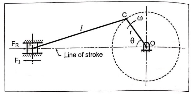
Consider a reciprocating engine mechanism shown. As we have discussed in before section, the acceleration of reciprocating parts is given by ![]()
where,
m = Mass of the reciprocating parts,
ω = Angular speed of the crank,
r = Radius of the crank,
θ = Angle of inclination of the crank with the line of stroke
l = Length of the connecting rod, and
n = Ratio of length of the connecting rod to the crank radius = l/n
It may be noted that in reciprocating engine mechanism, the inertia. Therefore the effect of inertia force should be eliminated for balancing. Therefore unbalanced force FU is given by
![]()
![]()
In above equation, the first term, mω² r cos θ is called as primary unbalanced force and the second term, ![]() is called as secondary unbalanced force.
is called as secondary unbalanced force.
∴ Primary unbalanced force, FP = mω² r cos θ
and secondary unbalanced force, ![]()
Note : From the expressions of primary and secondary unbalanced forces, the following points can be observed:
- The primary unbalanced force is maximum when θ = 0° or 180°
![]()
2. The secondary unbalanced force is maximum when θ = 0°, 90°, 180° and 360°.
![]()
3. From points (1) and (2), we see that the maximum value of the secondary unbalanced force is 1/n times the maximum value of the primary unbalanced force.
4. As the value of n (l/r) usually much greater than unity, the secondary unbalance force is small compared with the primary unbalanced force. Therefore the secondary unbalanced force can be safely neglected for low and moderate speed engines.
5. In case of high speed engines, the secondary forces are of appreciable magnitude and cannot be neglected.
6. Maximum value of the secondary unbalanced force occurs four times a revolution [see point (2)] as compared with twice per revolution for maximum primary unbalanced force [see point (1)]. In other words, we can say that the frequency of secondary unbalanced force is twice that of primary.
- See More : Natural frequency of free transverse vibrations
- See More : Laser Doppler Anemometer (LDA)
- See More : Bellows pressure sensor working


