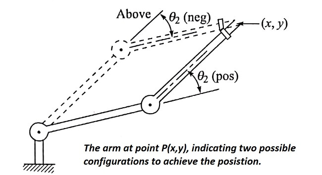
In many cases it is more important to be able to derive the joint angles given the end-of-arm position in world space. The typical situation is where the robot’s controller must compute the joint angles required to move its end-of-arm to a point in space defined by the point’s coordinates.
For the two-link manipulator we have developed, there are two possible configurations for reaching the point (x,y), as shown in fig.
This is so because the relation between the joint angles and the end effector coordinates involve ‘sine’ and ‘cosine’ terms. Hence we can get two solutions when we solve the two equations as given in the section above.
Some strategy must be developed to select the appropriate configuration. One approach is that employed in the control system of the Unimate PUMA robot.
In the PUMA’s control language, VAL, there is a set of commands called ABOVE and BELOW that determines whether the elbow is to make an angle θ2 that is greater than or less than zero, as illustrated in fig.
For our example, let us assume the θ2 is positive as shown in fig. Using the trigonometric identities,
cos (A + B) = cos A cos B – sin A sin R
sin (A + B) = sin A cos B + sin B cos A

we can rewrite Eqs
x = L1 cos θ1 + L2 cos θ1 cos θ2 – L2 sin θ1 sin θ2
y = L1 sin θ1 + L2 sin θ1 cos θ2 – L2 cos θ1 sin θ2
Squaring both sides and adding the two equations yields
![]()
Defining α and β as in fig we get

Using the trigonometric identity
![]()

we get
![]()
Knowing the link lengths L1 and L2 we are now able to calculate the required joint angles to place the arm at a position (x,y) in world space.
| Read More Topics |
| Robot sensors and actuators |
| Types of robot control |
| Configuration of robot controller |
| Robot applications |


