Scanning electron microscopy utilises electron beam for producing high-resolution images of sample surfaces. It forms 3-D view of the sample. It also gives the surface topography of the sample with sufficient clarity and depth of field.
The most common SEM mode is detection of the secondary electrons emitted by the atoms excited by the electron beam. The number of detectable secondary electrons depends on sample topography (the angle at which electron beam meets the sample surface).
A special detector is used for scanning the sample and collecting the emitted secondary electrons, after which an image is formed revealing the sample topography.
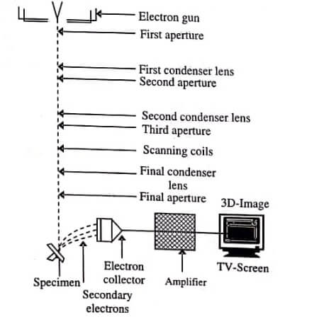
The basic construction of SEM (figure) is discussed below:
Electron Gun : It produces an electron beam. A filament (cathode) of 0.1 mm thin tungsten wire is heated at high temperature of about 2800 K to emit thermoelectrons.
Electromagnetic Lenses : A magnetic lens is also used in an electron microscope. When a direct electric current is passed through a coil-wound electric wire, a rotationally-symmetric magnetic field is formed and a lens action is produced on an electron beam.

Condenser and Objective Lenses : A condenser lens is mounted below the electron gun to adjust the electron beam’s diameter. Two-stage lenses combining the condenser and objective lenses are present below the electron gun.
The electron beam coming from the electron gun is focused by the two-stage lenses, producing a small electron probe.
If the action of condenser lens is strengthened, the electron probe becomes narrower; while if the action is weakened, the electron probe becomes broader. Between the condenser and objective lenses, the aperture is present. This aperture consists of a thin metal plate, having a small hole.
The electron beam after passing through the condenser lens illuminates the aperture-plate, which directs a part of electron beam towards the objective lens. This lens is used for focusing and determining the final diameter of the electron probe.
Specimen/Sample Stage : Since, the sample is observed at a high magnification, the stage should firmly support the sample and should move smoothly.
The sample stage can perform the following movements :
- Horizontal movement (X,Y),
- Vertical movement (Z),
- Specimen tilting (T), and
- Rotation (R).
X and Y movements are used for selecting a field of view; and Z movement is used for changing the image resolution and depth of focus. The construction of a sample stage is shown in figure.
Secondary Electron Detector : It detects the secondary electrons emitted from the sample. The tip of the detector is coated with a scintillator (fluorescent substance) and a high voltage of about 10kV is applied to it.
This high voltage attracts the secondary electrons which hit the scintillator, producing light. A light guide direct 5 this light to a Photo-Multiplier Tube (PMT), where it is converted into electrons to be amplified as an electric signal.
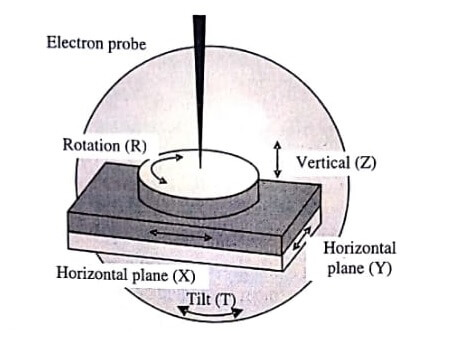
Image Display and Recording : The signals obtained from the secondary electron detector are amplified and transferred to the display unit. The scanning on display unit is synchronised with the electron-probe scan, thus brightness variation depends on the number of secondary electrons, appears on the monitor screen on the display unit.
As a result, a Scanning electron microscopy (SEM) image is formed. Earlier Cathode-Ray Tube (CRT) was in use as a display unit; but in recent years, a Liquid-Crystal Display (LCD) is being used.
The working of scanning electron microscopy (SEM) is shown with a ray diagram in figure. A narrow electron beam from the electron gun is directed to the sample to rapidly scan its surface.
As a result the sample releases secondary electrons, whose intensity depends on the shape and chemical composition of the irradiated object. A detector collects these secondary electrons and generates electrical signals, which are scanned to produce an image on a cathode ray tube.
SEM utilises a scanned electron beam and electromagnetic lenses for focusing and directing the beam on the sample surface. The electron beam and the sample surface interact and produce information in the form of signals, collected using detectors.
The output signals from these detectors modulate the monitor screen to form an image, corresponding to the small raster (a rectangular pattern of parallel scanning lines followed by the electron beam on a television screen) and information, pixel by pixel, originating from the sample surface.
Applications
- It is widely used in scientific and industry-related fields, especially where characterisations of solid materials is required.
- It provides information related to sample topography, morphology, and composition.
- It helps in detecting surface fractures providing information in microstructures, analysing surface contaminations, revealing spatial variations in chemical compositions, providing qualitative chemical analyses, and identifying crystalline structures.
- It also has practical industrial and technological applications such as semiconductor inspection, production line of miniscule products, and assembly of microchips for computers.
- It is used as an essential research tool in life science, biology, gemmology, medical and forensic science, and metallurgy.
Advantages
- It has a wide range of applications, and provides detailed 3-D and topographical imaging, and versatile information collected from detectors.
- It can be operated easily with proper training; and advances in computer technology and related software make its operation user-friendly.
- Its working is fast.
- The technological modifications made in the modern SEM generate data in digital form.
Disadvantages
- It is expensive, Iarge, and should be assembled in an area free of any possible elec̈tric, magnetic, or vibration interference.
- Its maintenance involves keeping a steady voltage, currents to electromagnetic coils, and cool water circulation.
- It demands well trained operators; even for sample preparation.
- It is limited to small solid, inorganic samples which can fit within the vacuum chamber and can withstand moderate vacuum pressure.
- It also carries a risk of radiation exposure associated with electrons emitted by the sample surface.
| Read More Topics |
| Quantitative Measurement of Bacterial Growth |
| Single cell isolation methods |
| Isolation method for pure culture of bacteria |
| Morphological classification of bacteria |