Strain Gauge Displacement Sensor
The strain gauge displacement sensor consists of a structure attached with the strain gauge that elastically deforms when subjected to a displacement. Strain gauge is attached to the object by a suitable adhesive. As the member is stressed, the resulting strain deforms the strain gauge attached with the structure. This causes an increase in resistivity of the gauge which produces electrical signal proportional to the deformation.
The change of resistance is very small and is usually measured using a Wheatstone bridge circuit where the strain gauge is connected into the circuit with a combination of four active gauges for full bridge, two gauges for half bridge, or a single gauge for quarter bridge. In the half and quarter circuits, the bridge is completed with precision resistors. The basic configuration, where the strain gauge is one leg of the bridge i.e., quarter bridge. As stress is applied to the bonded strain gauge, a resistive change takes place and unbalances the Wheatstone bridge. The change in the resistance of a bonded strain gauge is usually less than 0.5%. This changes of the resistance per unit resistance (ΔR\R) is proportional to the strain ε. It is given by the relation,
∆RR=G×∈
Where,
G is the constant of proportionality and is termed as gauge factor
R is the resistance of the undeformed gauge
ΔR is the change in resistance caused by strain, and
ε is strain
For metallic foil gauges, the gauge factor is usually taken as 2, For a single active gauge and three dummy resistors, the output V from the bridge is
V=B×G×∈4
Where B is the bridge excitation voltage.
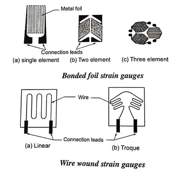
A wide variety of gauge sizes and grid shapes are available. The metallic strain gauge consists of a very fine wire or metallic foil arranged in a grid pattern. The grid pattern maximizes the amount of metallic wire or foil subject to strain in the parallel directions. The cross sectional area of the grid is minimized to reduce the effect of shear strain and Poisson strain. The grid is bonded to a thin backing, called the carrier, which is attached directly to the test specimen. The majority of stain gauges are bonded foil types, available in a wide choice of shapes and sizes to suit a variety of applications and typical examples. They consists of a pattern of resistive foil which is mounted on a backing material. They operated on the principle that as the foil is subjected to stress, the resistance of the foil changes in a defined way. Bonded foil strain gauges cn be as small as 16 mm2 and have a strain sensitivity or “gauge factor” of 2. Wire wound gauges are made of round wire of copper nickel, chrome nickel or nickel iron alloys, about 0.0025 in diameter. The length of wire is 25 mm or less. The example of wire wound strain gauges.
The environment considerations focus mainly on the temperature of the gauge. Since the resistance is a function of temperature the strain gauges are susceptible to variations in temperature. Thus, if it is known that the temperature of the gauge will vary due to any influence, temperature compensation is required in order to ensure that the force measurement is accurate.
- See More : Strain Gauge load cell
- See More : Lubrication system in IC engine
- See More : Non-destructive testing of weldments
- See More : Electrical comparator working
