There are three methods used in ultrasonic testing. They are,
- Pulse echo method
- Through transmission, and
- Resonance method
In pulse echo method, the reflected ultrasonic waves are used to identify and characterize the flaw. In through transmission method, the transmitted beam will be used to identify and characterize the flaw. The above three methods are normally employed in industries for ultrasonic testing.
Pulse echo method
Principle
Pulse echo method is the most popular and commonly used method to detect the imperfections like holes, cracks [flaws], air bubbles, etc.. In this method, a single probe is used for transmission and reception of the ultrasonic signal.
Description
This Pulse echo technique equipment consists of an ultrasonic frequency generator, a piezo – electric transducer, an amplifier and a CRO. The frequency generator is connected to the transducer. The transducer is tightly coupled to the specimen without any air gap. The whole set up is connected to the amplifier and to the CRO.
Working
- The frequency generator produces a high frequency and is applied to the piezo electric transducer. The Piezo electric transducer produces ultrasonic waves.
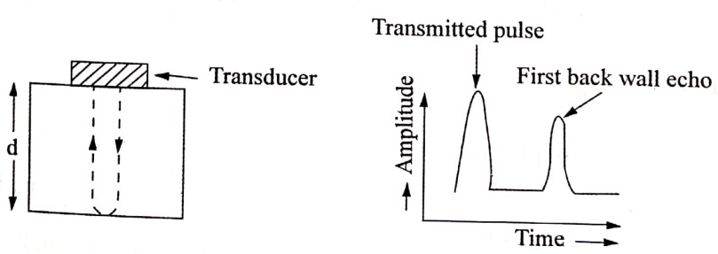
- To identify the defects in the specimen, the CRT screen is first calibrated between the transmitted pulse ( initial signal) and the time of arrival of the first back wall signal.
- When there is no defect in the specimen, the transmitted and back wall echo will appear as shown in fig.1.1 a.
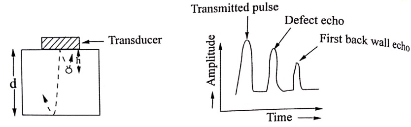
- If there is any defect in the specimen, a part of the ultrasonic wave gets reflected from the defect and a part at the back of the specimen.
- The reflected signals from the defect appear in between the transmitted pulse and back wall echo.
- From the time delay between the transmitted and received pulses, the position of the hole can be found.
- From the height of the pulse received, the depth of the hole can also be determined. The time domain traces obtained in this case is as shown in fig.1.1 b.
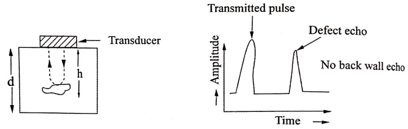
- When the defect is larger in the specimen, the entire signal is reflected by the defect and hence there is no back wall signal. The observed time domain traces is as shown in Fig.1.1c.
Advantages
-
The distance and location of defects can be analysed.
-
Simple and low cost inspection method.
-
Fast and reliable method of NDT.
Disadvantages
-
No permanent records of defects can be made.
-
Air gap between the test probe and specimen may affect the display.
Transmission method
Principle
It is a NDT method in which two probes are used. The first probe generates the ultrasonic signals and is known as transducer. The second probe receives the signal and is known as receiver.
Description
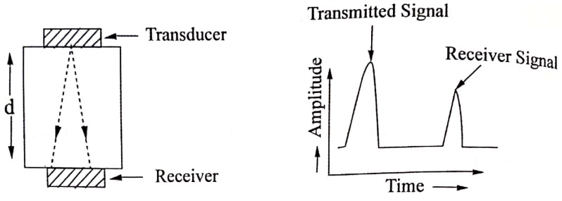
It consists of a Transmitter [T] and a Receiver [R] connected in opposite sides of the specimen. Both the transducers are connected to CRO to display the pulses produced by them.
Working
- The ultrasonic waves are transmitted by the transmitting transducer though the specimen. The ultrasonic waves are received by the receiving transducer in the other end and convert them into electrical pulse. This electrical pulse is fed to the CRO from the transmitter.
- When there is no defect in the specimen, the receiving probe receives maximum amount of transmitted signal from the specimen. Both transmitting and receiving probe are in maximum amplitude as shown in (Fig.1.2 a).
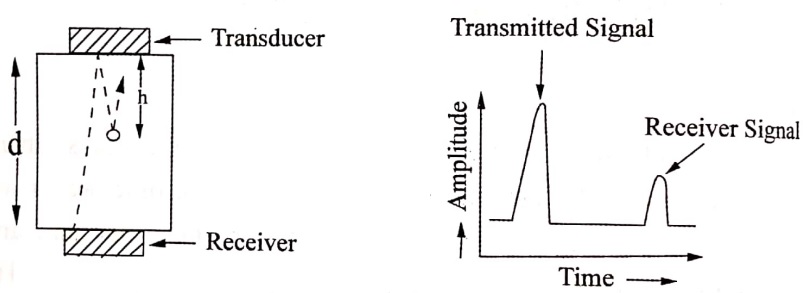
- If there is any defect in the specimen, the receiving probe receives less amount of transmitted signal from the specimen. Thus, there is a decrease in pulse amplitude of the received signal. This decrease is due to a small amount of energy get absorbed by the defect (flaw) as shown in (Fig.1.2 b)
- When the defect is larger in the specimen, the receiving probe receives no amount of transmitted signal from the specimen. Thus, there is a no pulse amplitude of the received signal from the receiver as shown in (Fig.1.2 c).

Advantage
-
Simple and low cost inspection method.
-
Its ability to inspect the defects such as large ingots and castings in high attenuation materials.
Disadvantages
-
This method provides only qualitative assessment of the defects and not the actual size and location.
-
This method requires good couplant.
-
Two probes are required for testing.
Resonance method
Principle
Generally, in any materials one can obtain the resonance condition when the thickness of the material is equal to half of the wave length of ultrasonic sound i.e., t=λ/2. This phenomenon is used to detect the defects in the material.
Description
This system consists of a transducer which is connected to the specimen and a CRO with transmitting, and receiving [reflection] input signals.
Working
- The transducer produces ultrasonic waves which is transmitted through the specimen.
- These waves get reflected by the opposite end of the specimen.
- Thus, the transmitted and reflected waves are interfere with each other.
- Then, by adjusting the frequency of the ultrasonic waves, standing waves are created.
- When there is no defect in the specimen, the material vibrates at its resonance frequency with a maximum amplitude, due to the formation of standing waves inside the specimen.
- If there is any defect in the specimen, there is a change in resonance frequency.
- The wavelength of the ultrasonic wave depends on the frequency. Therefore, one can create the condition of resonance for the thickness of the plate under test by varying the frequency of the ultrasonic waves.
- The condition of resonance is easily recognised by the increase of received pulse amplitude. The thickness can be obtained from the relation.

Where, v is the ultrasonic velocity in the specimen and f is fundamental frequency of the resonance.
| Read More Topics |
| Magnetostriction oscillator method |
| Photonics introduction and properties of laser |
| Comparison of musical sound and noise |