In this section we’ll introduce a new kind of unified modeling language UML diagram: the state diagram (also called the statechart diagram).
The UML class diagrams we examined in earlier chapters show relationships between classes. Class diagrams reflect the organization of the program’s code. They are static diagrams, in that these relationships (such as association and generalization) do not change as the program runs.
However, it’s sometimes useful to examine the dynamic behavior of particular class objects over time. An object is created, it is affected by events or messages from other parts of the program, it perhaps makes decisions, it does various things, and it is eventually deleted. That is, its situation changes over time. State diagrams show this graphically.
Everyone is familiar with the concept of state when applied to devices in our everyday lives. A radio has an On state and an Off state. A washing machine might have Washing, Rinsing, Spinning, and Stopped states. A television set has a state for each channel it is currently receiving (the Channel 7 Active state, and so on).
Between the states are transitions. As a result of a timer having reached (say) the 20-minute point, the washing machine makes a transition from the Rinse state to the Spin state. As a result of a message from the remote-control unit, the TV makes a transition from the Channel 7 Active state to the Channel 2 Active state.
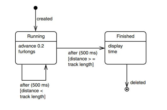
Figure shows a state diagram based on the HORSE program seen earlier in this chapter. It shows the different states a horse object can find itself in as the program runs.
States
In Unified Modeling Language UML state diagrams, a state is represented by a rectangle with rounded corners. The state is named at the top of the rectangle. State names usually begin with a capital letter. Below the name are any activities the object performs when it enters the state.
State diagrams can include two special states: a black disk represents the initial state, and a black disk surrounded by a circle represents the final state. These are shown in the figure.
After it is created, a horse object can be in only two major states: before it reaches the finish line it’s in the Running state, and afterwards it’s in the Finished state.
Unlike classes in a class diagram, there’s nothing in a program’s code that corresponds exactly to states in a state diagram. To know what states to include, you must have an idea what circumstances an object will find itself in, and what it will do as a result. You then make up appropriate names for the states.
Transitions
Transitions between states are represented by directed arrows from one rectangle to another. If the transition is triggered by an event, it can be labeled with the event name, as are the created and deleted transitions in the figure. Transition names are not capitalized. The names can be closer to English than to C++ usage.
The event that triggers the other two transitions is the timing out of a 500 millisecond timer. The keyword after is used to name these transitions, with the time as a parameter.
Transitions can also be labeled with what the UML calls a guard: a condition that must be satisfied if the transition is to occur. Guards are written in brackets. The two after() transitions have guards as well as event names. Because the events are the same, the guards determine which transition will occur.
Note that one of these transitions is a self transition: it returns to the same state where it began.
| Read More Topics |
| Radiographic inspection |
| Radio over fiber link |
| Nuclear power plant |