Basics of serial communication
The serial communication port is full duplex, meaning that it can transmit and receive simultaneously. It is also a receive buffered, meaning that it can commence reception of the second byte before a previously received byte has been read from the receive register. The serial communication port receive and transmit registers are both accessed at special function register SBUF. “Writing to SBUF” loads the transmit register and “reading from SBUF” accesses a physically separate receive register.
Different modes of serial data communication
The serial port can operate in 4 modes. They are
- Mode 0 : 8 – bit shift register
- Mode 1: 8- bit UART (Universal Asynchronous Receiver Transmitter)
- The Mode 2: 9 – bit UART (Fixed baud rate)
- Mode 3: 9 – bit UART ( Variable baud rate)
In all four modes, the transmission is initiated by any instruction that uses SBUF as a destination register. Reception is initiated in Mode 0 by the condition RI = 0 and REN = 1, in other modes it is initiated by the incoming start bit, if REN = 1.
If is are written to PD and IDL at the same time, PD takes precedence. In idle mode, the internal clock signal is gated off to the CPU, but not to the Interrupt, Timer and
Serial communication port functions. The PSW, Acc, and all other registers maintain their data during idle mode.
In the power down mode, the on-chip oscillator is stopped. With the clock frozen, all functions are stopped but the on chip RAM and SFRs are held.
There are two ways to terminate the Idle. They are
- Activation of interrupt
- Hardware reset
The only exit from power down is a hardware reset.
SFRs used in serial communication
- The SMOD bit in special function register PCON is used to set the baud rate of serial communication. It is a double baud rate bit. When this bit is set to 1, the baud rate is doubled, when the serial port is used in either mode 1, 2 or 3.
- The serial port control and status register is the special function register SCON. This register contains not only the mode selection bits, but also the 9th data bit for transmit and receive
(TB8 and RB8), and the serial port interrupt bits (TI and RI) - The values placed in timer – registers of TH1 and TL1 are used to set the baud rate of serial communication operates in mode and mode 3.
- The serial data buffer (SBUF) contains two independent registers of a transmit buffer register and a receive buffer register. Transmit buffer register is a parallel in serial out register, used for transmission. Similarly receive buffer register is a serial in parallel out register used for reception.
Modes of operation
The serial port of microcontroller 8051 can operate in four modes. In all four modes, transmission is initiated by any instruction that uses SBUF as a destination register. Reception is initiated in Mode 0 by the condition RI = 0 and REN = 1. Reception is initiated in other modes by the incoming start bit if REN = 1.
MODE 0 (8 bit Shift Register)
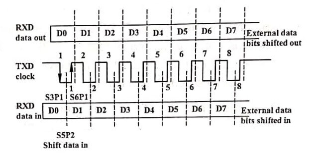
In this mode serial data enters and exits through RXD and TXD outputs the shift clock 8 bits are transmitted/ received. It contains only 8 data bits (LSB first). The baud rate is fixed at 1/12 the oscillator frequency. The timing for mode 0 shift register data transmission is shown in the image.
Transmission is initiated by any instruction that uses SBUF as a destination register. At the 10th machine cycle after “write to SBUF” the TI flag is set. SHIFT CLOCK is low during S3, S4 and S5 of every machine cycle and is high during S6, S1 and S2.
Reception is initiated by the condition REN = 1 and RI = 0. At the 10th machine cycle after REN = 1 and RI = 0, RI flag is set.
MODE 1 (8 bit UART)
In this mode 10 bits are transmitted through TXD or received through RXD. The data contains a start bit (0), 8 data bits (LSB first) and a stop bit (1). The baud rate is variable.

Multiprocessor communications
Modes 2 and 3 have a special provision for multiprocessor communications. In these modes, 9 data bits are received. The 9th one goes into RB8, then comes a stop bit.
The port can be programmed such that when the stop bit is received, the serial port interrupt will be activated only if RB8 = 1. This feature is enabled by setting bit SM2(1) in SCON. By using this feature a master processor can transmit a block of data to one of several slaves.
SM2 has no effect in Mode O. In Mode 1, it can be used to check the validity of the stop bit. In a Mode 1 reception, if SM2 1. the receive interrupt (RI) will not be activated unless a valid stop bit is received.
RS 232 serial interface standard
RS-232C is a serial interface standard. It is developed by Electronic Industries Association (EIA). This standard describes the functions of 25 signals and handshake pins for serial data transfer.
It also describes the voltage levels, the impedance levels, rise and fall times, maximum bit rates and maximum capacitance for these signals.
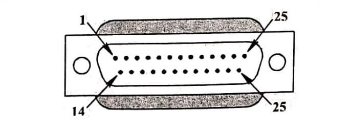
RS-232C is used to interconnect data communication equipment (DCE) and data terminal equipment (DTE). The DCE is the modem or modem elimintor (for direct connections without the use of modems) and DTE is the computer or peripheral device. This interface uses a 25-pin connector known as DB-25P (male connector) or DB- 25S (female connector).


