Analog Link
In telecommunication networks the trend has been to analog link telephone exchanges with digital circuits. A major reason for this was the introduction of digital integrated-circuit technology which offered a reliable and economic method of transmitting both voice and data signals. Since the initial applications of fiber optics were to telecommunication networks, its first widespread usage has involved digital links. However, in many instances, it is more advantageous to transmit information in its original analog form instead of first converting it to a digital format. Some examples of this are microwave-multiplexed signals,’ subscriber services using hybrid fiber/coax (HFC), video distribution, radio-over-fiber antenna remoting-10 and radar signal processing. For most analog applications, one uses laser diode transmitters, so we shall concentrate on this optical source here.
When implementing an analog fiber optic system, the main parameters one needs to consider are the carrier-to-noise ratio, bandwidth, spur free dynamic range, and signal distortion resulting from nonlinearities in the transmission system. This section describes the general operational aspects and components of an analog fiber optic link. Traditionally, in an analog system a carrier-to-noise ratio analysis is used instead of a signal-to-noise ratio analysis, since the information signal is normally superimposed on a radio-frequency (RF) carrier.
Thus, in next post we examine carrier-to-noise ratio requirements. This is first done for a single channel under the assumption that the information signal is directly modulated onto an optical carrier. For transmitting multiple signals over the same channel, one can use a subcarrier modulation SCM technique. In this method, which is described in this post, the information signals are first superimposed on ancillary RF subcarriers. These carriers then are combined and the resulting electrical signal is used to modulate the optical carrier. A limiting factor in these systems is the signal impairment arising from harmonic and intermodulation distortions.
In SCM techniques the RF subcarriers are multiplexed in the electrical domain and then are superimposed on an optical carrier. For example, these could be the 6-MHz video signals used in CATV systems. As a result of the emerging use of broadband wireless communication devices, schemes have been investigated and implemented for using analog optical fiber links for distributing broadband microwave-frequency signals in a variety of applications. The methods for transmitting microwave analog signals in the 0.3-to-300-GHz range over an optical fiber link have become known as RF-over. fiber techniques. Next post examines the basics of these techniques. Next gives of an example radio-over-fiber links to distribute millimeter-wave radio services to customers.
To enable the efficient application of RF-over-fiber techniques, the field of microwave photonics into existence. Research in this field encompasses the study and applications of photonic devices came operating at microwave frequencies. In addition to device developments, microwave photonics also addresses optical signal processing at microwave speeds and the design and implementation of RF photonic transmission systems. This section gives a brief overview of microwave-photonic components and their uses.
Overview of Analog Links
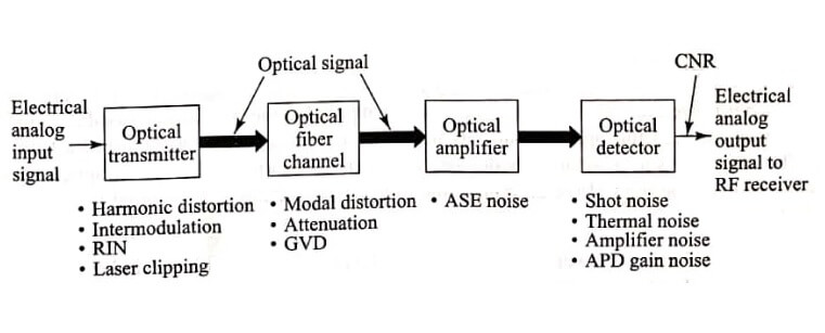
Image shows the basic elements of an analog link. The transmitter contains either an LED or a laser diode optical source. As noted in Sec and shown in image, in analog applications, one first sets a bias point on the source approximately at the midpoint of the linear output region. The analog signal can then be sent using one of several modulation techniques. The simplest form for optical fiber links is direct intensity modulation, wherein the optical output from the source is modulated simply by varying the current around the bias point in proportion to the message signal level. Thus, the information signal is transmitted directly in the baseband.
A somewhat more complex but often more efficient method is to translate the baseband signal onto an electrical subcarrier prior to intensity modulation of the source. This is done using standard amplitude- modulation (AM), frequency-modulation (FM), or phase-modulation (PM) technique. No matter which method is implemented, one must pay careful attention to signal impairments in the optical source. These include harmonic distortions, intermodulation products, relative intensity noise (RIN) in the laser, and laser clipping.
In relation to the fiber-optic element shown in image, one must take into account the frequency dependence of the amplitude, phase, and group delay in the fiber. Thus, the fiber should have a flat amplitude and group-delay response within the passband required to send the signal free of linear distortion. In addition, since modal-distortion-limited bandwidth is difficult to equalize, it is best to choose a single-mode fiber. The fiber attenuation is also important, since the carrier-to- noise performance of the system will change as a function a of the received optical power.
The use of an optical amplifier in the link leads to additional noise, known as amplified spontaneous emission (ASE), as is described in this chapter. In the optical receiver, the principal impairments are quantum or shot noise, APD gain noise, and thermal noise.
| Read More Topics |
| Communication channel |
| Natural frequency of free torsional vibration |
| Basic communication system |


