The following alignment tests are carried on lathe.
- Levelling of the machine.
- True running of location cylinder of main spindle.
- Axial slip of main spindle and true running of shoulder face of spindle nose.
- True running of headstock center.
- Parallelism of main spindle to saddle movement.
- True running taper socket in main spindle.
- Movement of upper slide parallel with main spindle in vertical plane.
- Parallelism of tailstock guide ways with the movement of carriage.
- Parallelism of tailstock sleeve taper socket to saddle movement.
- Pitch accuracy of lead screw.
- Alignment of lead screw bearings with respect to each other.
Levelling of the machine
It is done by a sensitive spirit level. The saddle is kept approximately in the centre of the bed support feet.
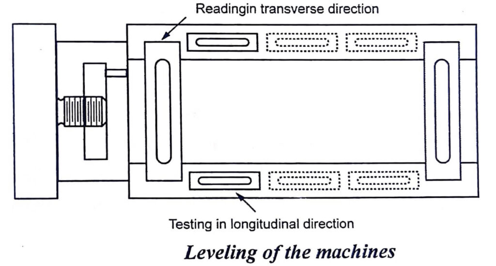
The spirit level is then placed at a-a to ensure the level in the longitudinal direction. For test in transverse direction, the spirit level is placed on a bridge piece.
True running of locating cylinder of main spindle
Locating cylinder is provided to locate the chuck or face plate. For providing locating cylinder, the locating surface should be in cylindrical shape.
The dial indicator is fixed to the carriage and the feeler of the indicator touches the locating surface. Then the surface is rotated on its axis and indicator should not show any movement of spindle.
Axial slip of main spindle and true running of shoulder face of spindle nose
Axial slip is defined as the axial spindle movement which follows the same pattern and is due to manufacturing error. So the above mentioned test is meant to check this error.
True running of headstock centre
The true running of headstock is measured by using the dial indicator. The dial indicator is pressed perpendicular to the taper surface of the centre as shown in fig.
Parallelism of the main spindle to saddle movement
It should be done in both vertical and horizontal planes. Mandrel is used for checking the parallelism. If axis of the spindle is not parallel to bed in a horizontal direction, a tapered surface is produced.
For this test, a mandrel is fitted in the taper socket of the spindle.
Mandrel has a concentric taper shank which fits closely to the spindle nose taper, dial indicator feeler is pressed on the mandrel and the carriage is moved.
The indications in horizontal plane are shown in dial (b) and vertical plane is shown by dial (a).
True running of taper socket in main spindle
If the axis of socket tapered hole is not concentric with the main spindle axis, eccentric jobs will be produced.
This test is done by using a mandrel by fitting into the tapered hole. The readings are taken in both extremes of the mandrel.
Movement of upper slide parallel with main spindle in vertical plane
It is done by fixing the dial indicator in the tool post. A mandrel is fitted in the spindle. The dial gauge feeler is pressed against the mandrel in vertical plane and the upper slide is moved longitudinally.
This type of error is not tested in horizontal plane because there is swiveling arrangement for taper turning.
Parallelism of tailstock guideways with the movement of carriage
If the axis of job is not coincide with the tailstock centre, there will be some offset of the tailstock centre and it results in taper turning.
A block is placed on the guideways as shown in fig to check the parallelism of tailstock guide ways.
The feeler of the indicator is touched on the horizontal and vertical surfaces of the block. The dial indicator is held in the carriage and the carriage is moved. Suppose, if error occurs while checking, it will be indicated on the dial indicator.
Parallelism of tailstock sleeve to saddle movement
If the tailstock sleeve is not parallel to the saddle movement, the height of dead centre would vary as varying lengths of sleeve taken out.
When job is held between the live centre and dead centre, it is necessary that the central axis of the dead centre be coaxial with the job axis in both the planes. If it is not like this, the job may be fitted up or down or in sideways due to the support of the dead centre.
The test is carried out by fixing the dial indicator on the tool post. The plunger is pressed against the sleeves first in vertical and then in horizontal plane. The deviations are indicated by dial indicator.
Pitch accuracy of lead screw
The thread accuracy depends upon the accuracy of its lead screw. So, the uniformity of the lead screw throughout its length is very important.
The test for checking the accuracy of lead screw is performed by fixing a positive stop on the lathe bed. The length bars and slip gauges are located against the stop.
An indicator is mounted on the carriage. The initial loading of the dial gauge against the slip gauge is noted.
Then the slip gauges are removed and the carriage is connected to the lead screw and lead screw is disconnected from the gear train. An indexing arrangement is utilized for rotating the lead screw.
The distance traveled by carriage is equal to the length of slip gauges.
The measurement reading is noted by the dial indicator recorded. The care must be taken not to disturb the datum location when the gauges change for different pitch lengths.
Alignment of lead screw bearing with respect to each other
The position of the lead screw is decided by the alignment of bearing. Misalignment of lead screw i.e., it not being parallel to the bed in vertical plane or horizontal plane can cause additional stresses due to bending when carriage is moved.
- See More : Horizontal axis wind turbine
- See More : Vertical axis wind turbine
- See More : Devices used for measurement
- See More : Straightness measurement


