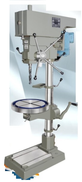
The various test performed in pillar type drilling machine are,
- Flatness of clamping surface of base.
- Flatness of clamping surface of table.
- Perpendicularity of drill head guide to the base plate.
- Perpendicularity of drill head guide with table.
- Perpendicularity of spindle sleeve with base plate.
- True running of spindle taper.
- Parallelism of the spindle axis with its vertical movement.
- Squareness of clamping surface of table to its axis.
- Total deflection.
Flatness of clamping surface of base
It is performed by placing a straight edge on two gauge blocks on the base plate in various positions. The feeler gauge is used to find the error.
Flatness of clamping surface of table
It is performed by placing a straight edge on two gauge blocks on the table.
Perpendicularity of drill head guide to the base plate
This test performed by placing the frame level on guide column and base plate. Errors are noted by noting the difference between the readings of the two levels.
Perpendicularity of drill head guide with table
It is performed by placing the frame level on guide column as mentioned in the previous error checking and the permissible error is 0.15/1000mm.
Perpendicularity of spindle sleeve with base plate
It is performed in both the planes specified in test (3) and the difference that the frame levels are to be placed on spindle sleeve and base plate. But, this error should not exceed 0.25/1000mm for sleeve which should be inclined toward column only.
True running of spindle taper
In this test, the mandrel is placed in the tapered hole of spindle and dial indicator is fixed on the table and its feeler is made to scan the mandrel.
The readings are taken by rotating the spindle and the error should not exceed 0.03/100mm for machines with taper up to Morse No – 2.
Parallelism of the spindle axis with its vertical movement
It is done on two planes at right angles to each other. The test mandrel is fitted in the tapered hole of the spindle and the dial indicator is fixed on the table with its feeler touching the mandrel.
The readings are taken by adjusting in the middle position of its travel. The dial indicator readings are taken when the spindle is moved in upper and lower directions.
Squareness of clamping surface of table to its axis
In this test, the dial indicator is mounted in the tapered hole of the spindle and its feeler is made to touch the surface of table. The readings are taken by slowly rotating the table.
Total deflection
In this test, the pillar type drilling machine head and table are arranged in their middle position. Dial indicator is mounted on table with its feeler touching the lower machined surface part.
The dynamometer is attached with the drill spindle and the deflection of dial indicator is noted down.
