The performance of a radio receiver is measured on the basis of its selectivity, sensitivity, fidelity and image frequency rejection.
Selectivity
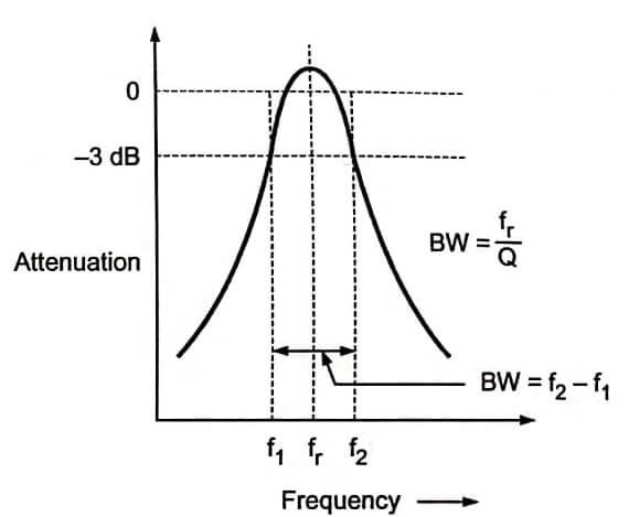
The selectivity is the ability of the receiver to select a signal of a desired frequency while rejecting all others. The selectivity of the receiver is obtained partially by RF amplifier and mainly by IF amplifiers. The selectivity shows the attenuation that the receiver offers to signals at frequencies near to the one to which it is tuned. Fig shows the typical selectivity curve of the receiver. The selectivity depends upon tuned LC circuits used in RF and IF stages. ƒr is the resonating (tuned) frequency and Q is quality factor of these LC circuits. As shown in fig, bandwidth should be narrow for better selectivity. Hence Q of the coil should be high.
Sensitivity
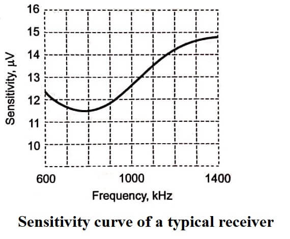
The ability of the receiver to pick up weak signals and amplify them, is called sensitivity. It is often defined interms of the voltage that must be applied to the receiver input terminals to give the standard output power, measured at the output terminals. As the gain of the receiver is increased, sensitivity is also increased. The sensitivity is expressed in microvolts or decibels.
Fig shows the typical sensitivity curve of a receiver. As shown in the figure, the sensitivity is decreased (voltage is increased) at higher frequencies.
Fidelity
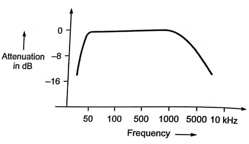
The ability of the radio receiver to reproduce all the range of modulating frequencies equally is called fidelity of the receiver. Fig shows typical fidelity curve of the receiver. The fidelity curve shown in the figure basically. represents frequency response of the receiver. The curve should be nearly flat over the required range of frequencies. A good fidelity Fig Typical fidelity curve requires wide band of frequencies to be amplified. Hence for good fidelity, more bandwidth of RF and IF stages is required. But this results in poor selectivity. AM receivers are not good fidelity receivers, since bandwidth in AM is low.
Image Frequency Rejection
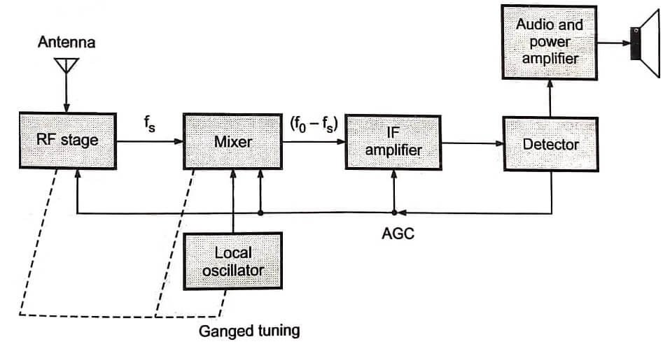
We know that local oscillator frequency is made higher than the signal frequency such that ƒ0 – ƒs = ƒi. Here ƒi is IF. That is ƒ0 = ƒs + ƒi . The IF stage passes only ƒi. If the frequency ƒsi – ƒs + 2ƒi appears at the input of the mixer, then the mixer will produce difference frequency equal to ƒi. This is equal to IF. The frequency ƒsi is called image frequency and is defined as the signal frequency plus twice the IF. This image frequency is converted in the IF range and it is also amplified by IF amplifiers. This is the effect of two stations being received simultaneously. The image frequency rejection is done by tuned circuits in the RF stage. It depends upon the selectivity of the RF stage. The image rejection should be done before the IF stages.
- See More : Superheterodyne receiver
- See More : Single mode fiber connectors
- See More : Series capacitor voltage
