Operational Amplifiers (usually called ‘op amps’) were originally made from discrete components, being designed to solve mathematical equations electronically, by performing operations such as addition and division in analogue computers. Now produced in integrated-circuit (IC) form, op amps have many uses, with one of the most important being as a high-gain d.c. and a.c. voltage amplifier.
The main properties of an op amp include:
- a very high open-loop voltage gain Ao of around 105 for d.c. and low frequency a.c., which decreases with frequency increase
- a very high input impedance, typically 106 Ω to 1012 Ω, such that current drawn from the device, or the circuit supplying it, is very small and the input voltage is passed on to the op amp with little loss
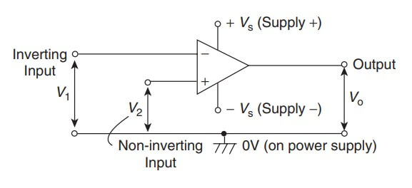
- a very low output impedance, around 100 Ω, such that its output voltage is transferred efficiently to any load greater than a few kilohms. The circuit diagram symbol for an op amp is shown in figure It has one output, Vo , and two inputs; the inverting input, V1 is marked −, and the non-inverting input, V2, is marked +
The operation of an op amp is most convenient from a dual balanced d.c. power supply ±Vs (i.e. +Vs, 0, − Vs); the centre point of the supply, i.e. 0V, is

common to the input and output circuits and is taken as their voltage reference level. The power supply connections are not usually shown in a circuit diagram.
An op amp is basically a differential voltage amplifier, i.e. it amplifies the difference between input voltages V1 and V2.
Three situations are possible:
(i) if V2 > V1, Vo is positive
(ii) if V2 < V1, Vo is negative
(iii) if V2 = V1, Vo is zero

where Ao is the open-loop voltage gain.
| Read More Topics |
| Maximum power transfer theorem |
| Conduction in semiconductor materials |
| Introduction to electromagnetic induction |
| Magnetic field due to an electric current |


