There are a number of situations when digital signals have to be converted to analogue ones. For example, a digital computer often needs to produce a graphical display on the screen; this involves using a D/A converter to change the two-level digital output voltage from the computer, into a continuously varying analogue voltage for the input to the cathode ray tube, so that it can deflect the electron beam to produce screen graphics.
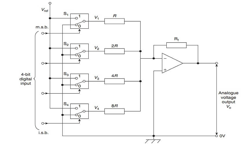
A binary weighted resistor D/A converter is shown in figure for a four-bit input. The values of the resistors, R, 2R, 4R, 8R increase according to the binary scale – hence the name of the converter. The circuit uses an op amp as a summing amplifier with a feedback resistor Rf. Digitally controlled electronic switches are shown as S1 to S4.
Each switch connects the resistor in series with it to a fixed reference voltage VREF when the input bit controlling it is a 1 and to ground (0V) when it is a 0. The input voltages V1 to V4 applied to the op amp by the four-bit input via the resistors therefore have one of two values, i.e. either VREF or 0V.

The analogue output voltage Vo is given by:
![]()
Let Rf = R = 1 kΩ, then:
![]()
With a four-bit input of 0001 (i.e. decimal 1), S4 connects 8R to VREF, i.e. V3 = VREF, and S1, S2 and S3 connect R, 2R and 4R to 0V, making V1 = V2 = V3 = 0. Let VREF = −8 V, then output voltage,
![]()
With a four-bit input of 0101 (i.e. decimal 5), S2 and S4 connects 2R and 8R to VREF, i.e. V2 = V4 = VREF, and S1 and S3 connect R and 4R to 0V, making V1 = V3 = 0.
![]()
Again, if VREF = −8 V, then output voltage,
If the input is 0111 (i.e. decimal 7), the output voltage will be 7V, and so on. From these examples, it is seen that the analogue output voltage, Vo, is directly proportional to the digital input. Vo has a ‘stepped’ waveform, the waveform shape depending on the binary input. A typical waveform is shown in Fig.
| Read More Topics |
| Op AMP Voltage comparator |
| Two port networks and characteristic impedance |
| Maximum power transfer theorem |
| Force on a current carrying conductor |


