Introduction to Alternator Voltage Regulator Excitation System
When the load on the power system changes, alternator voltage regulator the terminal changes. Therefore, to maintain the terminal voltage of the generator excitation of the generator must be decreased voltage within permissible standards, the or increased depending upon the situation prevailing to protect the devices or apparatus which is operating in the power system. This can be achieved by employing automatic voltage regulator (AVR).
The basic function of an excitation system is to provide direct current to the synchronous machine. In addition, the excitation system performs control and protective functions essentially to the satisfactory performance of the power system by controlling the field voltage, thereby the field current.
The control function include, the control of voltage and reactive power flow and the enhancement of system stability. The protective function ensures that the capability limits of the synchronous machine, excitation system and other equipment are not exceeded.
In addition to voltage regulators at generator buses static shunt capacitors, synchronous compensators, static VAR systems, tap changing transformers are also used in the power system for rapid alternator voltage regulator.
Exciter Ceiling Voltage
It is the maximum voltage that may be attained by an exciter under specific conditions.
Excitation System Ceiling Voltage
It is the maximum D.C. component system output voltage that is able to be attained, by an excitation system under specified conditions.
Excitation System Requirements
The excitation system must satisfy the following requirements.
- Meet specified response criteria.
- Must be able to prevent damage to itself, generator and its associated equipments.
- It should have good operating flexibility.
- Meet the desired reliability and availability by incorporating the necessary levels of redundancy, internal fault detection and isclation capability.
Types of Excitation System – Alternator Voltage Regulator
Based on excitation power source used, the excitation system can be classified as :
- D.C. Excitation systems.
- A.C. Excitation systems.
- Static Excitation systems.
D.C. Excitation Systems
This excitation system utilizes D.C generators as sources of excitation power and provide current to the rotor of the synchronous machine through slip rings.
The D.C. excitation systems were used in the earlier days. Now it has been superseded by A.C. exciters.
A.C. Excitation System
This excitation system uses alternators (A.C. machines) as sources of the main generator excitation power. Usually, the exciter is on the same shaft as the turbine generator.
The A.C. output or the exciter is rectified by either controlled or un-controlled rectifiers, to provide the direct current for the generator field.
Static Excitation Systems
The components in these systems are static or stationary. The static rectifier either controlled or un-controlled, supply the excitation current directly to the field of the main synchronous generator through slip rings. The main source of power to the rectifiers is from the main generator through a transformer to step down the voltage to an required level. At the time of starting, the field is supplied through battery power.
Potential Controlled – Rectifier Excitation System
The exciter system shown in image is an example of static excitation system. The field current of the main generator is obtained from the main generator itself through exciter transformer. The variable field voltage is obtained through an controlled rectifier, and the firing angle of thyristors is determined by the main generator terminal voltage.

The field winding is supplied through slip rings. This system is advantageous as it is small inherent time constant, inexpensive and easily maintainable.
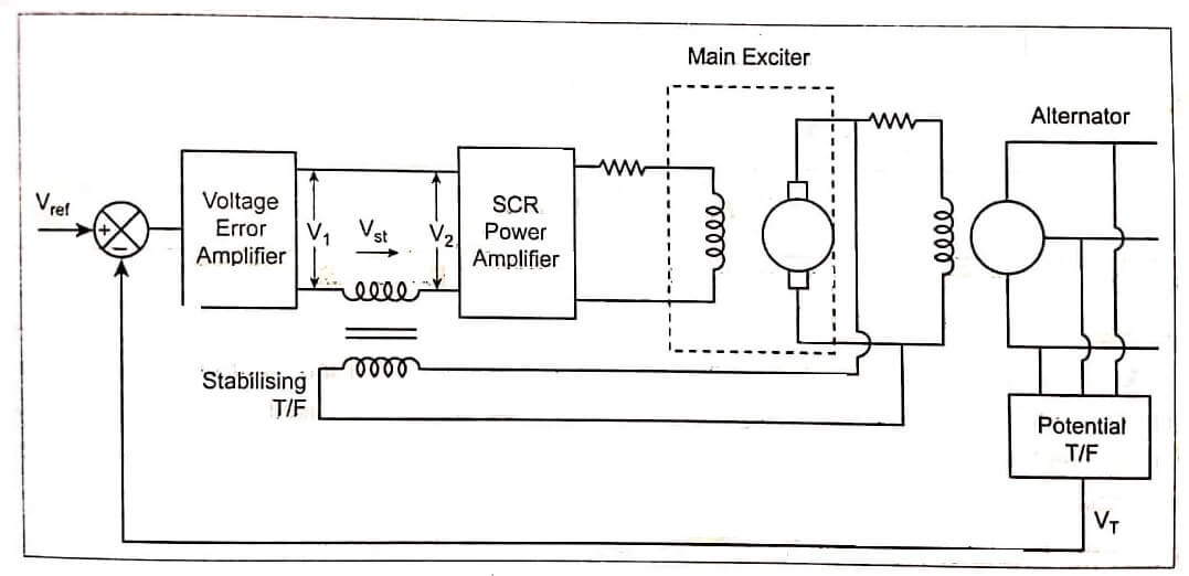
Alternator Voltage Regulator Excitation System
The excitation system consists of main exciter (a D.C. generator) which excites the alternator field to control the output voltage. The exciter field is automatically controlled through error signal
e = V ref – VT
V ref = Reference signal
VT = Potential transformer output voltage.
The error signal is amplified through voltage amplifier. The error signal firing angle of the thyristors which depends upon terminal voltage. Thus, the specified voltage is obtained at the alternator output. The stabilizing transformer is used in addition to the error signal to dump system excitations. The schematic diagram of alternator voltage regulator is shown in image.
| Read More Topics |
| Series capacitor voltage |
| Methods of voltage control |
| Reactive power and voltage |