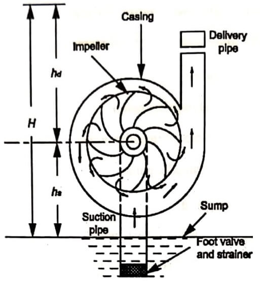
Centrifugal pumps are the devices which convert the mechanical energy into hydraulic energy by means of centrifugal force acting on the fluid. Centrifugal pumps are classified as roto dynamic type of pumps in which a dynamic pressure is developed to lift liquids from lower level to higher level. The basic working principle of centrifugal pump is that when a certain mass of liquid is made to rotate by an external force, it is thrown away from the central axis of rotation and a centrifugal pressure is developed which raises the liquid to higher level.
Classification of Centrifugal Pumps
Based on their utility, design and constructional features, centrifugal pumps can be classified as follows
- Shape and type of casing
- Volute or spiral casing
- Vortex or whirlpool casing
- Volute casing with guide blades.
- Working head
- Low head (up to 15m)
- Medium head (15m to 40m)
- High head (over 40m).
- Number of stages
- Single stage centrifugal pumps
- Multi stage centrifugal pumps.
- Liquid handled
- Closed impeller pump
- Semi closed impeller pump
- Open impeller pump.
- Specified speed
- Low specific speed pumps
- Medium specific speed pumps
- High specific speed pumps.
- Number of entrances to the impeller
- Single suction or single entry pump
- Double suction or double entry pump.
Main Components of a Centrifugal Pump
A centrifugal pump consists of the following elements,
- Impeller
- Casing
- Suction pipe, strainer and foot valve
- Delivery pipe and delivery valve.
Impeller :
A rotating element consists of a vaned rotor called impeller. The impeller is mounted on a shaft which connects to the shaft of an electric motor. The vanes of the impeller may be curved, cylindrical or have more complex surfaces. But generally, series of backward curved vanes are equally spaced around the periphery of the shaft. The unit has a finite number of vanes, usually six to twelve. The impellers are of any one of the following three types.
Shrouded or closed impeller:
Figure (a) shows this type of impeller in which vanes are provided with metal cover plates or shrouds on both sides. The closed impeller provides a better guidance for the liquid and is more efficient.
Semi open type impeller:
Figure shows this type of impeller in which vanes has only the base plate and no crown plate.

Open impeller:
Figure (c) shows the types of impeller in which vanes have neither the crown plate nor the base plate. The vanes are open on both sides.
Casing:
It is an air tight chamber surrounding the impeller. It is similar to the casing of a reaction turbine. It contains suction and discharge arrangements and supporting for bearings. The essential purposes of casing are
- to guide water to and from the impeller, and
- to partially convert the kinetic energy into pressure energy.
Suction pipe, strainer and foot valve:
Suction pipe connects the centre (eye) of the impeller to the sump from which the liquid is to be lifted. The pipe is air tight so that there is no possibility of formation of air pockets. Suction pipe is provided with a strainer at its lower end so as to prevent the entry of solid particles, debris etc. into the pump.
The foot valve is a one-way valve located above the strainer into the suction pipe. It is used to fill the pump with liquid before it is started (i.e., priming) and it prevents back flow, when the pump is stopped.
Delivery pipe and delivery valve:
One end of the delivery pipe is connected to the outlet of the pump and the other end delivers the liquid to the required height. A regulating valve provided just near the pump outlet serves the control liquid flow.
- See More : Hydraulic and pneumatic system
- See More : Eddy current or indicator dynamometer
- See More : Gas turbine power plant
- See More : Hydro electric power plants
