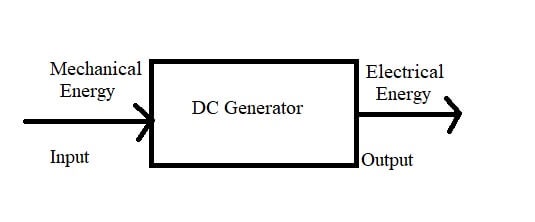
DC Generator : An electrical generator is a rotating machine which converts mechanical energy into electrical energy. It is shown in figure. This energy conversion is based on the principle of electromagnetic induction. According to Faraday’s laws of electromagnetic induction, whenever a conductor is moved in a magnetic field, dynamically induced e.m.f is produced in the conductor.
When an external load is connected to the conductor the induced e.m.f. causes a current to flow in the load. Thus the mechanical energy which is given in the form of motion to the conductor is converted into electrical energy. If a single conductor is used the e.m.f. produced is small. Large number of conductors are used to obtain greater e.m.f. and the rotating conductor assembly is called an armature.
Parts of a DC Generator
Figure shows as DC generator with its major parts as given below.
- Magnetic frame or Yoke
- Poles, interpoles, windings, pole shoes
- Armature
- Commutator
- Brushes, bearings and shaft Magnetic frame
Magnetic frame
The magnetic frame or yoke serves two purposes.

- It acts as a protecting cover for the whole machine and provides mechanical support for the poles.
- It carries the magnetic flux produced by the poles. The flux per pole divides at the yoke so that the yoke carries only half the flux produced by each pole.
In small machines where cheapness is the main consideration and weight is not a critical factor, the yoke is made up of cast iron. But for large machines where weight is the main consideration, cast steel or rolled steel is used. Since the permeability of steel is double that of cast iron, the area of cross section of yoke and hence the weight is reduced by half.

Poles
The poles consist of (i) pole cores (ii) pole shoes and (iii) pole coils. The pole cores and pole shoes form the field magnet. The end of the pole core towards the armature is often expanded in the form of shoe to reduce the reluctance of the air gap since the cross section becomes larger at the bottom. Since the poles are electromagnets a field winding is wound over the pole core. The pole coils are made up of copper wire or strip. When current is passed through these coils the pole becomes an electromagnet and starts establishing a magnetic field in the machine. The flux distribution through the pole, airgap, armature core and yoke is shown in figure.
For very small machines the poles are made up of cast iron. For larger machines cast steel is used. To minimize eddy current losses, the pole is laminated. Sheet steel laminations are used for this.
Interpoles
In modern D.C machines commutating poles or interpoles are provided to improve commutation. Just like the field winding, the commutating poles also have exciting coils which are connected in series with the armature. Since they carry full armature current, the coils are made up of fewer turns of thicker conductor to reduce the resistance.
Armature
The armature consists of an armature core and armature windings. The armature core houses the armature conductors or coils. The armature along with the conductors rotates under the poles and hence the flux produced by the field magnets is cut by the armature conductors.

When the conductors rotate, they alternatively come under the influence of north and south poles. This causes high hysteresis losses in the armature core. To reduce losses, low hysteresis steel containing a few percentage of silicon is used in the armature.
When the armature core rotates in the pole fleax, eddy currents are also produced in it. If a solid iron armature is used, an emf is induced in an axial direction and iron being a conductor would result in large circulating current called eddy current to flow in the core. This produces unnecessary heat which results in heavy power loss. To minimize the eddy current losses the armature core is laminated. In between laminations insulation is provided. The laminations are about 0.4 mm to 0.5 mm thick. The laminations are often known as stampings. In small machines these stampings are directly keyed on to the shaft. In larger machines the stampings are first assembled and then keyed on to an armature spider and the armature spider is then keyed on to the shaft. By so doing, the amount of material is reduced and free air can be circulated through the centre of the armature.

The eddy current losses and hysteresis losses produce considerable heat in the armature, and spacers. Ventilating ducts may be necessary to remove this heat. Sometimes a fan is provided at one end of the armature for good ventilation. The armature conductors are usually made up of copper and are housed in the slots provided in the armature. The slots are rectangular in shape for large machines and circular for small machines; the conductors are housed in slots in two layers. The slots are closed by fiber or wooden wedges to prevent the conductors from flying out due to centrifugal force, when the armature rotates. The arrangement is shown in figures.
Steel binding wires are also wound over the armature surface for additional protection. The slots are well insulated to avoid any short circuit between the armature and the conductors. The armature conductor is insulated by single cotton cover or double cotton cover or by enamel.
Commutator
The commutator converts the alternating emf into unidirectional or direct emf. It is made up of wedge shaped segments or hard-drawn or drop forged copper, insulated from each other by thin layers of built-up mica. A simple commutator is shown in figure.

The segments are held together by clamping flanges that pull the segments inward when the flanges are drawn together by bolts and cap screws. The flanges are further insulated from the segments by two rings of built-up mica. The armature coil leads are soldered to each commutator segment by a riser.
Brushes and Bearings
The brushes, which are made up of carbon or graphite, collect the current from the commutator and to convey it to the external load resistance. They are rectangular in shape. These brushes are housed in brush holders and mounted over brush holder studs. The brush holder studs are mounted on a brush yoke or, rocker arm. The brush holder studs are insulated from the brush yoke by insulation sleeves. Ball bearings are usually employed as they are reliable for light machines. For heavy duty machines roller bearings are used. The bearings are packed in hard oil for quicker operation.
[sc_fs_faq html=”true” headline=”h2″ img=”” question=”What is the basic principle of a DC generator?” img_alt=”” css_class=””] Basic principle of a DC generator is Faraday’s law of electromagnetic induction. Whenever a conductor is moved in a magnetic field, dynamically induced emf is produced in that conductor. [/sc_fs_faq]
- See More : Hydraulic system and models
- See More : Computer control of power system
- See More : Alternate voltage regulator
- See More : Automatic voltage regulator


