Sources : In circuit analysis, the goal is to start with a connected set of circuit elements such as resistors, capacitors, operational amplifiers, and other devices, and to find the voltages across and currents through each element, additional quantities, such as power dissipated, are often computed. To energize the circuit, sources of electric energy must be connected. Sources are modeled in various ways.

One convenient classification is to consider constant (dc) sources, sinusoidal (ac) sources, and general time-varying sources. The first two are of interest in this section.
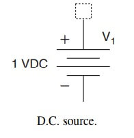
DC Sources : Some sources, such as batteries, deliver electric energy at a nearly constant voltage, and thus they are modeled as constant voltage sources. The term dc sources basically means directcurrent sources, but it has come to stand for constant sources as well. Figure shows the standard symbol for a dc source. Other sources are modeled as dc current (or constant-current) sources. Figure (b) and c show the symbols used for these models.
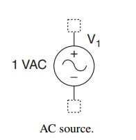
AC Sources : Most of the electric energy used in the world is generated, distributed, and utilized in sinusoidal form. Thus, beginning with Charles P. Steinmetz, a German-American electrical engineer, much effort has been devoted to finding efficient ways to analyze and design circuits that operate under sinusoidal excitation conditions. Sources of this type are frequently called ac (for alternating current) sources. Figure shows the standard symbol for an ac source. The most general expression for a voltage in sinusoidal form is of the type
v(t) = Vm cos (2πƒt + α) = Vm cos (ωt + α)
and, for a current
i(t) = Im cos (2πƒt + β) = Im cos (ωt + β)
Some writers use sine functions instead of cosine functions, but this has only the effect of changing the angles α and β.
These expressions have three identifying characteristics, the maximum or peak value (Vm or Im), the phase angle (α or β), and the frequency [ƒ, measured in hertz (Hz) or cycles per second, or ω, measured in radians/second]. A powerful method of circuit analysis depends on these observations. It is called phasor analysis.
| Read More Topics |
| Introduction of synchronous machines |
| Alternator construction and working |
| Single phase induction motor |
| History of circuit switcher development |


