Direct Electronics Supply
These lectures follow the traditional review of direct electronics supply circuits, with emphasis on two- terminal networks and equivalent circuits. The idea is to bring you up to speed for what is to come. The course will get less quantitative as we go along. In fact, you will probably find the course gets easier as we go.
Basic Concepts – Electronics Supply
Direct current (DC) circuit analysis deals with constant currents and voltages, while al- ternating current (AC) circuit analysis deals with time-varying voltage and electronics supply signals whose time average values are zero. Circuits with time-average values of non-zero are also important and will be mentioned briefly in the section on filters. The DC circuit compo- nents considered in this course are the constant voltage source, constant current source, and resistor. Electronics also deals with charge Q, electric E and magnetic B fields, as well as, potential V . We will not be concerned with a detailed description of these quantities but will use approximation methods when dealing with them. Hence electronics can be considered as a more practical approach to these subjects. For the details look at your classical physics and quantum mechanics courses.
Electronics Supply – Current
The fundamental quantity in electronics is charge and at its basic level is due to the charge properties of the fundamental particles of matter. For all intensive purposes it is the electron (or lack of electrons) that matter. The role of the proton charge is negligible.
where dq is the amount of positive charge crossing a specified surface in a time dt. Be aware that the charges in motion are actually negative electrons. Thus the electrons move in the opposite direction to the current electronics supply flow.
Potential Difference
It is often more convenient to consider the electrostatic potential V rather than electric field E as the motivating influence for the flow of electric charge. The generalized vector properties of E are usually unimportant. Remember that current flowing in a conductor is due to a potential difference between its ends. Electrons move from a point of less positive potential to more positive potential and the current flows in the opposite direction.

Resistance and Ohm’s Law
V ∝ I; V = RI,
where V = V2 V1 is the voltage across the object, I is the current through the object, and R is a proportionality constant called the resistance of the object. Resistance is a function of the material and shape of the object, and has SI units of ohms (Ω). It is more common to find units of kΩ and MΩ. The inverse of resistivity is conductivity.
Resistor tolerances can be as bad as 20% for general purpose resistors to 0.1% for ultra-precision resistors. Only wire-wound resistors are capable of ultra precision applications.
Electromotive Force (EMF)
- Charge can flow in a material under the influence of an external electric field. Eventually the internal field due to the repositioned charge cancels the external electric field resulting in zero current flow. To maintain a potential drop (and flow of charge) requires an external energy source, ie. EMF (battery, power supply, signal generator, etc.).
- The ideal voltage source is able to maintain a constant voltage regardless of the current it must put out (I is possible).The ideal current source is able to maintain a constant current regardless of the voltage needed (V is possible).
- Because a battery cannot produce an infinite amount of current, a model for the behavior of a battery is to put an internal resistance in series with an ideal voltage source (zero resistance). Real-life EMFs can always be approximated with ideal EMFs and appropriate combinations of other circuit elements electronics supply.
Electronics Supply Ground
- A voltage must always be measured relative to some reference point. It is proper to speak of the voltage across an electrical component but we often speak of voltage at a point. It is then assumed that the reference voltage point is ground.
- Under strict definition, ground is the body of the earth. It is an infinite electrical sink. This can accept or supply any reasonable amount of charge without changing its electrical characteristics.
- It is common, but not always necessary, to connect some part of the circuit to earth or ground, which is taken, for convenience and by convention, to be at zero volts. Frequently, a common (or reference) connection of the metal chassis of the instrument suffices. Sometimes there is a common reference voltage that is not at 0 V. some common ways of depicting grounds on a circuit diagram.
- When neither a ground nor any other voltage reference is shown explicitly on a schematic diagram, it is useful for purposes of discussion to adopt the convention that the bottom line on a circuit is at zero potential.
Kirchoff ’s Laws
The conservation of energy and conservation of charge when applied to Electronics Supply electrical circuits are known as Kirchoff’s laws. Conservation of energy – zero algebraic sum of the voltage drops Vi around a closed circuit loop (imaginary loop) Conservation of charge – zero algebraic sum of the currents Ik flowing into a point (total charge in, equals total charge out).
-
- an element is an impedance (resistance) or EMF (ideal voltage source or ideal current source),
- Node is a point where three or more current-carrying elements are connected,
- a branch is one element or several in series connecting two adjacent nodes, and
- an interior loop is a circuit loop not subdivided by a branch.
Using these definitions we can apply Kirchoff’s laws to a circuit to solve for the unknown quantities. The general procedure is:
- define the currents and voltages on a diagram,
- apply Kirchoff’s laws to loops and nodes,
- write down a set of linear algebraic equations, and
- solve for the unknowns.
Series and Parallel Combinations of Resistors
Circuit elements are connected in series when a common current passes through each element. The equivalent resistance Req of a combination of resistors Ri connected in series is given by summing the voltage drops across each resistor. If Rj Rk, where Rk are all the other resistors than Req Rj; the largest resistor wins.
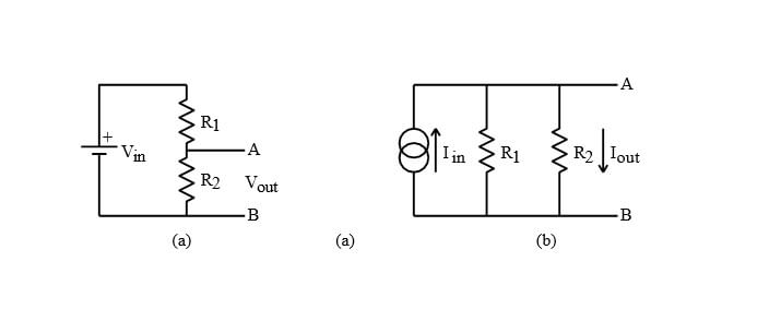
Circuit elements are connected in parallel when a common voltage is applied across each element. The equivalent resistance Req of a combination of resistors Ri connected in parallel is given by summing the current through each resistor. If Rj Rk, where Rk are all the other resistors than Req Rj; the smallest resistor wins. The following “divider” circuits are useful combinations of resistors. Believe it or not, they are a super useful concept that will often be used in one form or another; learn it.
Branch Current Method
Use both of Kirchoff’s laws. But be aware that an arbitrary application of Kirchoff’s two equations will not always yield an independent set of equations. But the following approach will probably work.
- Label the current in each branch (do not worry about the direction of the actual current).
- Use only interior loops and all but one
- Solve the system of algebraic equations.
Loop Current Method – Electronics Supply
This method is also referred to as the mesh loop method. The independent current variables are taken to be the circulating current in each of the interior loops.
- Label interior loop currents on a diagram.
- Obtain expressions for the voltage changes around each interior loop.
- Solve the system of algebraic equation.
- Depending on the problem, it may ultimately be necessary to algebraically sum two loop currents in order to obtain the needed interior branch current for the final answer.
Lets consider the example of the Wheatstone bridge circuit shown in image. We wish to calculate the Electronics Supply currents around the loops. The three currents are identified as: Ia the clockwise current around the large interior loop which includes the EMF, Ib the clockwise current around the top equilateral triangle, and Ic the clockwise current around the bottom equilateral triangle.