The electromotive force (e.m.f.), E, of a cell is the p.d. between its terminals when it is not connected to a load (i.e. the cell is on ‘no load’).
The e.m.f. of a cell is measured by using a high resistance voltmeter connected in parallel with the cell. The voltmeter must have a high resistance otherwise it will pass current and the cell will not be on ‘no-load’.
For example, if the resistance of a cell is 1Ω and that of a voltmeter 1 MΩ then the equivalent resistance of the circuit is 1 MΩ + 1 Ω, i.e. approximately 1 MΩ, hence no current flows and the cell is not loaded.
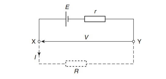
The voltage available at the terminals of a cell falls when a load is connected. This is caused by the internal resistance of the cell which is the opposition of the material of the cell to the flow of current. The internal resistance acts in series with other resistances in the circuit. Figure shows a cell of e.m.f. E volts and internal resistance, r, and XY represents the terminals of the cell.

When a load (shown as resistance R) is not connected, no current flows and the terminal p.d., V = E. When R is connected a current I flows which causes a voltage drop in the cell, given by Ir. The p.d. available at the cell terminals is less than the e.m.f. of the cell and is given by:
V = E – Ir
Thus if a battery of e.m.f. 12 volts and internal resistance 0.01Ω delivers a current of 100A, the terminal p.d.,
V = 12 − (100)(0.01)
= 12 − 1 = 11 V
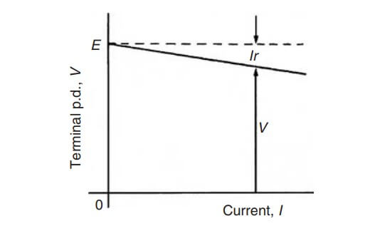
When different values of potential difference V across a cell or power supply are measured for different values of current I, a graph may be plotted as shown in Fig Since the e.m.f. E of the cell or power supply is the p.d. across its terminals on no load (i.e. when I = 0), then E is as shown by the broken line.

Since V = E − Ir then the internal resistance may be calculated from
![]()
When a current is flowing in the direction shown in Fig the cell is said to be discharging (E > V).
When a current flows in the opposite direction to that shown in Fig the cell is said to be charging (V > E).
A battery is a combination of more than one cell. The cells in a battery may be connected in series or in parallel.
For cells connected in series:
Total e.m.f. = sum of cell’s e.m.f.s
Total internal resistance = sum of cell’s internal resistances
For cells connected in parallel:
If each cell has the same e.m.f. and internal resistance:
Total e.m.f. = e.m.f. of one cell
Total internal resistance of n cells
![]()
| Read More Topics |
| Chemical effects of electric current |
| Electric current and quantity of electricity |
| Resistor colour coding and ohmic values |
| Electrical / electronic system block diagram |


