By using integral controller to the governor mechanism, the frequency control loop must be characterised by a sufficient degree of stability. Integral of the generators of the control are should divide the total load for optimum economy can be met only by optimal dispatch equation.
Frequency error = 0 for a step load charge
The primary ALFC loop makes the initial coarse readjustment of frequency. By using this, the various generators in the control area can be shared the load depends on their capacity.
Time taken for the primary loop to respond = 2 to 20 sec
The secondary ALFC loops over the fine adjustment of the frequency by using integral controller action. The frequency error should be zero. This loop operates after the primary loop has done its job
Response time = Order of 1 minute.
The optional dispatch of generation may be treated within the framework of ALFC. We consider economic dispatch control as the tertial control loop.
Digital computer is located in an energy control centre, which collects information like real power every five minutes through communication channels, telephone, microwave, etc.
The digital computer is included in the control loop which scans the power generation of units and the line flows. These settings are compared with the optional settings derived from the solution of the economic dispatch program.
The output of the comparator is given to the computer which generates the raise/lower pulses which are sent to the individual speed governing mechanism, to readjust the megawatt generation accordingly.
Multi Area System
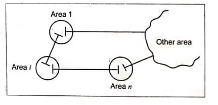
An interconnected power system is divided into a number of “control areas” for the purpose of load frequency control. When subjected to disturbances like a small load change, all the generator-turbine units in a control area swing together with the other groups of generator turbine units in other areas. Hence, all the units in a control area are represented by a single unit of equivalent inertia and characterized by a single (area) frequency. Since all the network is strong all the bus loads in a control area are assumed to act at single load point and characterized by a single equivalent load parameter. The different control areas are connected by relatively “weak” tie lines. A typical n-area power system.
For the optimal operation of an interconnected power system, the following points are to be considered.
- Under normal operating condition, each control area should have the capacity to meet its own load from its own spinning generator, plus the scheduled interchange between the neighboring areas.
- Under emergency condition, the energy can be drawn from the spinning reserves of all the neighbouring areas immediately due to the sudden loss of generating unit.
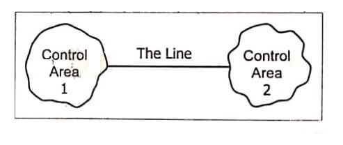
During normal operation of interconnected power system requires load frequency controller for each area which not only drives the area frequency, deviation to zero but also the “net interchange” of that area to zero under steady state condition. Net interchange of area is defined as the algebraic sum of tie line flows between area I and other connected areas with tie line flow out of area.
Two Area Load Frequency Control System Modelling
An extended power system can be divided into a number of load frequency control areas interconnected by means of tie lines. Without loss of generating, we shall consider a two area case connected by a single tie line as illustrated.
The control objective now is to regulate the frequency of each area and to simultaneously regulate the tie line power as per inter area power contracts. As in the case of frequency, proportional plus integral controller will be installed so as to give zero steady state error in the tie line flow as compared to the contracted power.
It is conveniently assumed that each control area can be represented by an equivalent turbine, generator and governor system. Symbols used with suffix ‘I’ refers to area ‘I’ and those with suffix ‘2’ refers to area ‘2’.
In an isolated control area case, the incremental power. (ΔPG –ΔPD) was accounted for by the rate of increase of stored kinetic energy and increase in area load caused by increase in frequency. Since a tie line transports power in or out of an area, this fact must be accounted for in the incremental power balance equation of each area.
| Read More Topics |
| Types of Deaerator |
| Nuclear power plant |
| Hydro electric power plant |
| Steam power plant |
