We know that the satellite can receive and transmit one of the bands given in Table For each band, the uplink and downlink frequencies are separate. Frequency division multiplexing of the complete uplink and downlink range of frequencies can be done to transmit and receive many channels simultaneously. For example for ‘C’ band, the bandwidth of 500 MHz for uplink and downlink is divided into 12 channels.
That is the satellite can receive and transmit these 12 channels simultaneously. But today, with the increasing number of channels to be transmitted via satellites, the bandwidth of satellites are short. And therefore more satellites are to be launched in the space. But the cost investment of building and launching one satellite is too heavy. Therefore it is necessary that for the given satellite and in the given bandwidth of that satellite try to accommodate as many number of channels as possible, in addition to FDM and TDM methods.
To preserve the bandwidth of the satellite links, it is beneficial to transmit additional carrier waveforms occupying the same bands using the same link. The concept of using the same frequency band to transmit separate carriers is called frequency re-use. There is no multiplexing involved in frequency re-use technique.
Since more than one carriers of the same frequency in the same link are used for transmission, the information capacity of the link increases without increasing the link bandwidth. The care should be taken that the carriers of the same frequency should not be mixed. The frequency re-use can be obtained by dual polarization of the frequency carrier or spot beams.
Frequency Re-use by Dual Polarization
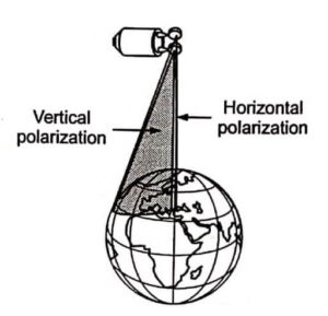
In TV transmission we have seen the concept of polarization of electromagnetic waves. Three types of polarizations are important : (a) Vertical, (b) Horizontal and (c) Circular. We know that the electromagnetic waves have two fields : electric field and magnetic field. In vertical polarization, the electric field is along the north south axis of the satellite. In horizontal polarization, the electric field is at 90° to the north-south axis of the satellite.
The electric field advances like a Cork Screw in circular polarization. The circular polarization can be left hand circular or right hand circular. Normally horizontal and vertical polarization are called linear polarization. The well known star TV channel broadcasted via satellite is vertically polarised.
In the concept of frequency re-use by dual polarization, the same band of frequencies are transmitted by placing each on orthogonal polarizations of the same field generated at the transmitter. Orthogonal polarization means they don’t have any common signals between them. Horizontal polarization and vertical polarization are orthogonal to each other.
Similarly right hand circular and left hand circular polarizations are orthogonal to each other. If two separate carriers of the same frequency but having orthogonal polarizations are transmitted, then the mixing or cross talk due to each other is not possible and true separation is maintained. The two carriers are received by aligning the receiving antenna for the particular polarization. If the antenna is aligned for vertically polarized carrier, then it rejects the horizontally polarized carrier and receives only vertically polarized carrier, eventhough the frequency band is same.
Thus with dual polarization, the carrier bandwidth can be transmitted with two different data modulations at the same time. This doubles the information capacity of the channel.
The atmospheric effects may affect the orthogonality of the two polarizations. This would cause the cross coupling of one channel into the other channel of the same frequency. This produces interference and crosstalk in the channels. This is called depolarization. The depolarization is negligible below 10 GHz. Therefore dual polarization is employed for satellites operating ‘C’ bands.
Frequency Re-use with Spot Beams
The downlink transmission from the satellite can cover the complete earth surface possible or any specific area. The transmitting antennas of the satellite are aligned so that only required area is covered by the satellite. As we know that uniform transmission may cover mountains and oceans also.
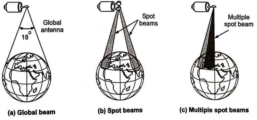
But transmission at mountains and oceans is useless except special applications like ship to ship communication and airlines. Special satellite channels are used for this type of communication. Therefore satellite downlink transmission is classified into beams. These beams are global, spot beams and zonal beams. The area served by these beams is called foot print area.
The global beam covers almost the maximum possible area. It is normally 42% of the earth surface. The transmitting antenna is designed such that it covers the complete facing area to the satellite. Global beam is used normally for telephone and fixed point communication. Global beam needs more power to be transmitted because area covered is large.
Zonal beams are normally used to cover the specific zone of the earth.

Eventhough the zonal beam covers small area compared to global beam, the transmitter power required is high. It is less compared to power required to transmit global beam. The zonal beams are used for Television and data broadcasting, telephone networks etc. For example, zonal beam is used by star TV channel to cover the Indian subcontinent and Gulf countries. Similarly zonal beam can be used for European countries.
Spot beams are used to cover a very small area by the satellite. These beams concentrate power into areas smaller than these covered by global beams. The signal to noise ratio within the beam is increased but the coverage area is small. The EIRP is more in spot beams compared to zonal and global beams. Multiple spot beams are used to increase the area covered.
Spot beams are normally used for point to point communications, control applications like control of airlines and ships etc. Fig shows the various types of beams.
The problem with the spot beams is that multiple antenna beams must be provided from the satellite. This increases the complexity of the satellite system. The beam pointing becomes more critical for earth stations using spot beams.

Spot beams can be used for frequency re-use to increase the channel capacity. Different information can be sent to different points using spot beams. These spot beams use the same carrier frequency, but do not cover the same area. This doubles the capacity of the channels. Fig (b) shows two spot beams covering different areas. These spot beams can use the same carrier frequency for downlink transmission. The crosstalk and interference effect does not arise because the beams are totally separate. If the separation between the multiple beams is not perfect, the problems of interference arise. Interference can be reduced by using separate frequency bands for adjacent beams. But this increases the required frequency range. The beam separation can also be obtained by orthogonal polarization of the carrier in the beams. The carrier frequency band used for two spot beams is same, but their polarization is orthogonal.
The receiver antennas are aligned to receive only one polarized beam. Even though the two beams they cover the same area as shown in Fig the interference Fig Frequency re-use by spot and crosstalk effects are reduced. The earth station beams and orthogonal polarization can receive both the beams separately. The depolarization of the carrier in the beams may cause some interference.
| Read More Topics |
| Code division multiple access |
| Geostationary earth orbit (GEO) |
| Electromagnetic waves |
| Basic communication system |


