Mechanical comparators are one form of linear measurement device which is quick and more convenient for checking large number of identical dimensions. Comparators normally will not show the actual dimensions of the work piece.
They will be shown only the deviation in size, during the measurement, a comparator is able to give the deviation of the dimension from the set dimension. It cannot be used as an absolute measuring device but can only compare two dimensions.
Comparators are designed in several types to meet various conditions. Comparators of all types incorporate some kind of magnifying device. The magnifying device magnifies how much dimension deviates, plus or minus from the standard size.
The comparators are classified according to the principles used for obtaining magnification. The common types are:
- Mechanical comparators
- Electrical comparators
- Optical comparators
- Pneumatic comparators
Mechanical comparators
Mechanical comparator employs mechanical means for magnifying small deviations. The method of magnifying small movement of the indicator in all mechanical comparators are effected by means of levers, gear trains or a combination of these elements.
Mechanical comparators are available having magnifications from 300 to 5000 to 1. These are mostly used for inspection of small parts machined to close limits.
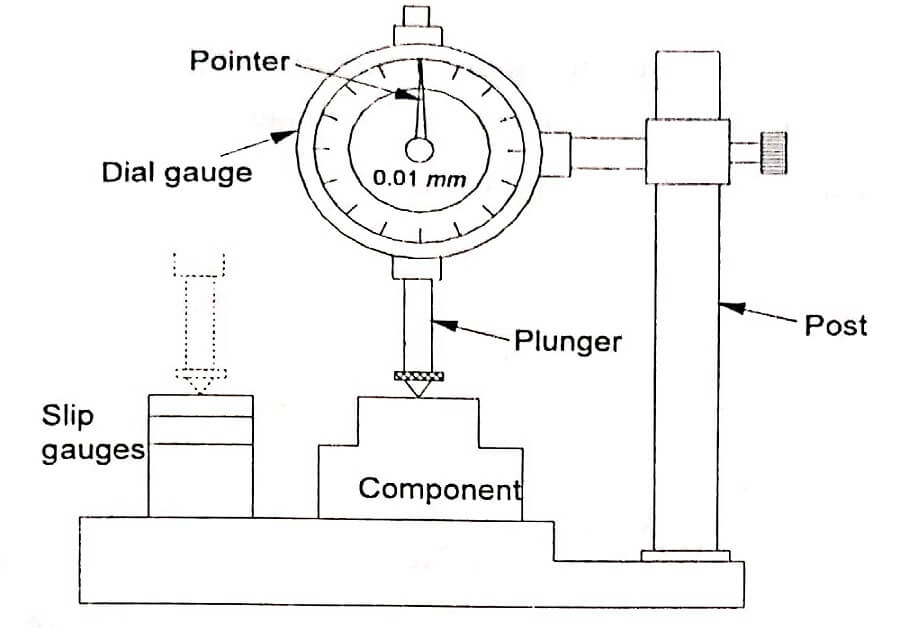
Dial indicator – A dial indicator or dial gauge is used as a mechanical comparator. The essential parts of the instrument are like a small clock with a plunger projecting at the bottom as shown in fig.
Very slight upward movement on the plunger moves it upward and the movement is indicated by the dial pointer. The dial is graduated into 100 divisions. A full revolution of the pointer about this scale corresponds to 1mm travel of the plunger.
Thus, a turn of the pointer by one scale division represents a plunger travel of 0.01mm.
Experimental setup : The whole setup consists of worktable, dial indicator and vertical post. The dial indicator is fitted to vertical post by on adjusting screw as shown in fig. The vertical post is fitted on the worktable.
The top surface of the worktable is finely finished. The dial gauge can be adjusted vertically and locked in position by a screw.
How to use?
Let us assume that the required height of the component is 32.5mm. Initially, this height is built up with slip gauges.
The slip gauge blocks are placed under the stem of the dial gauge. The pointer in the dial gauge is adjusted to zero. The slip gauges are removed.
Now, the component to be checked is introduced under the stem of the dial gauge. If there is any deviation in the height of the component, it will be indicated by the pointer.
The mechanism of such an instrument is illustrated in fig. The plunger has rack teeth. A set of gears engage with the rack. The pointer is connected to a small pinion. The small pinion is independently hinged.
It is not connected to the plunger. The vertical movement of the plunger is transmitted to the pointer through a set of gears. A spring gives a constant downward pressure to the plunger.
Read type mechanical comparator
In this type of comparator, the linear movement of the plunger is specified by means of reed mechanism. The mechanism of this type is illustrated in fig.
Initially, the comparator is set with the help of a known dimension set of slip gauges. Then the indicator reading is adjusted to zero.
When the part to be measured is kept under the pointer, then the comparator displays the deviation of this dimension either in + or – side of the set dimension.
Advantages:
- It is usually robust, compact and easy to handle.
- There is no external supply such as electricity, air required.
- It has very simple mechanism and is cheaper when compared to other types.
- It is suitable for ordinary workshop and also easily portable.
Disadvantages:
- Accuracy of the comparator mainly depends on the accuracy of the rack and pinion arrangement. Any slackness will reduce accuracy.
- It has more moving parts and hence friction is more and accuracy is less.
- The range of the instrument is limited since pointer is moving over a fixed scale.
- See More : Principles of clamping
- See More : Mechanical energy based process
- See More : Vertical axis wind turbine


