Principles of Clamping
Principles of clamping devices are used to hold the workpiece in the correct relative position in the jig or fixture. It should ensure that the workpiece is not displaced under the action of cutting forces.
For efficient operation, firm clamping of the workpiece is a must. An inadequate clamping may always prove dangerous. Clamping devices are designed for minimum operating and handling time.
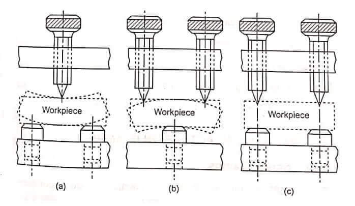
The following design and operational factors should be considered to achieve best results.
- (i) The applied clamping pressures against the workpiece must counteract the tool forces.
- The clamping force should be kept minimum. It must only hold the workpiece and should never be great enough so as to damage the workpiece.
- The clamping pressure should be exerted on the solid supporting part of the workpiece to prevent distortion.
- Clamping should be simple, quick operating and foolproof.
- The clamping pressure should be directed parallel to cutting operation. i.e., it should not be directed towards the cutting operation.
- The clamping pressure should be directed towards the support surface in order to prevent lifting of workpiece from its support.
- The movement of the clamp for loading and unloading purposes should be kept limited and if possible, it should be positively guided.
- As far as possible, a suitable device, such as a spring should always be incorporated to avoid lifting of the clamp by hand.
- The clamp should be arranged on the work to perform as many operations as possible in one setting.
- The clamp should be of robust construction so that it will not bend under pressure.
- The clamp should be case hardened to prevent the wear of clamping faces.
- The clamping faces should always be arranged directly above the work supports to avoid distortion of work.
- The clamping parts should be designed to make it non detachable from the jig.
- In case of handling soft or fragile workpiece, fiber pads are provided in clamping face to prevent damage to the work.
- The design should facilitate a complete separation of the clamp from the work to enable quick and unrestricted unloading and loading.
Clamping Devices
There are large numbers of different types of clamps. Clamps can be broadly classified into two types:
(i) Mechanical actuating clamps,
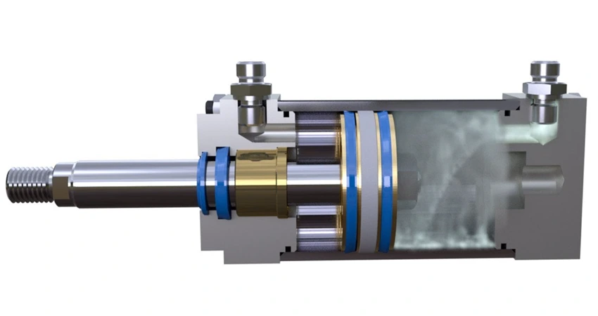
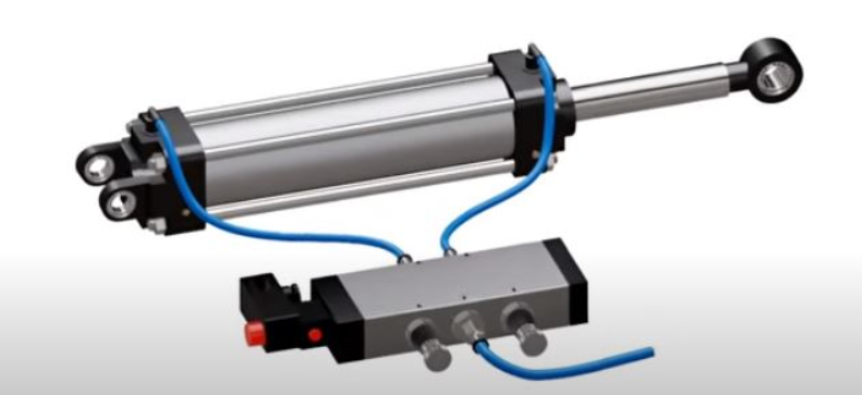
(ii) Power clamps.
Mechanical actuating clamps can be further classified into screw clamps, strap clamps, latch clamps, wedge or key clamps, cam clamps, hinged clamps, edge clamp, toggle clamps.
Mechanical Actuation Clamps – Principles of Clamping
Screw Clamps
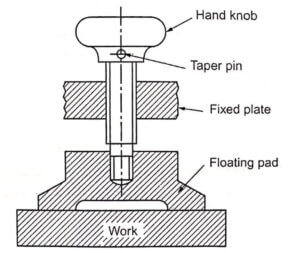
Screw clamps are the simple type of clamps and quite commonly used in jigs and fixtures. This clamp comprises of a screw, a hand knob, and a pressure pad. It works on the principle of bolt and nut.
The basic screw clamp uses the torque developed by a screw thread to hold a component in place.
The clamping area of a screw clamp can be increased by a provision for a pad. The clamping pad is free to rotate on the pivot. This eliminates friction between workpiece and pad.
The clamping pad remains stationary on the workpiece while the screw rotates and rubs on the conical seat of the pad.
These types of clamp are also known as clamping screws or clamp screws.
The force developed by the screw can be calculated by the following formula : F = PL/R tan(α+θ)
F = Force developed by screw
P = Pull or push applied to spanner
R = Pitch radius of screw thread
L = Leangth of spanner or lever
α = Helix angle of thread
θ = Friction angle of thread
Even though it has many advantages, they have following limitations also,
- Clamping force is not constant.
- Relatively larger effort is needed for clamping, resulting in fatigue to the operator.
- Time taken by clamping is more.
- There may be a tendency of producing indentations of the screw tip on workpiece in the absence of floating pads.
Strap clamp or Lever clamp
Strap clamps are simple in construction and operation, and can be economically manufactured. They operate on the principle of a lever.
The various designs in the strap type clamp used in jigs and fixtures are discussed below:
Bridge clamp: It is one of the very simple and reliable clamping devices. The basic elements of a bridge clamp are a solid heel, a strap, a stud, a spring and spherical washers.
The clamping force is applied by the springloaded nut, The stud is designed to have a safe diameter to withstand the clamping and cutting pressures and also the cross section of the strap.
In this type of a clamp, a pillar pin is integrated as a part of the jig or fixture body. Sometimes, it may also a separate part.
When the nut is unscrewed, the spring pushes the clamp towards. It facilitates the loading and unloading operation, Principles of Clamping.
In these clamps, the ratio of compressive force of the nut shared between the workpiece and clamp support depends on the following factors:
- Relative positions of the nut,
- The point of contact of the clamps with the work and with outer support.
- See More : Bend test for steel
- See More : Defects in welding
- See More : Press working terminology
- See More : Gas and Arc Welding process
