Memory Interfacing
While executing a program, the microprocessor needs to access memory frequently to read instruction code and data stored in memory; the interfacing circuit enables that access. Memory has some signal requirements to write into and read from its registers. Similary, the microprocessor initiates a set of signals when it wants to read from and write into memory. The memory interfacing process involves designing a circuit that will match the memory requirements with the microprocessor signals.
The primary function of memory interfacing is that the microprocessor should be able to read from and write into a given register of a memory chip.
I/O Interfacing
The Input/Output devices such as keyboards and displays are the communication channels to the outside world. Latches and buffers are used for I/O interfacing. They once hardwired, perform only one function (either as input device if it is buffer and as output device if it is a latch). Thus limiting their capabilities. To improve the overall system performance the Intel has designed various programmable I/O devices. Along with the I/O functions, they can perform many other functions such as time delays, counting and interrupt.
The programmable peripheral device is a combination of many devices on a single chip. The advantage of programmable device is that they can be set up to perform specific functions by writing a code in its internal register. As this code controls the function of the programmable device, it is called control word and the register in which it is stored internally is called control register.
Some of the peripheral devices developed by Intel for 8085/8086/8088 based system are:
8255 – Parallel Communication Interface
8251 – Serial Communication Interface
8254 – Programmable Timer
8279 – Keyboard / Display Controller
8257 – DMA Controller
8259 – Programmable Interrupt Controller
The microprocessor can communicate with external world or other systems using two types of communication interfaces.
- Serial Communication Interface
- Parallel Communication Interface.
Serial Communication Interface
The serial communication interface gets a byte of data from the microprocessor and sends it bit by bit to the other system serially or it receives data bit by bit serially from the external system, then it converts the data into bytes and sends to the microprocessor.
Parallel Communication Interface
A parallel communication interface gets a byte from the microprocessor and sends all the bits in that byte simultaneously (parallel) to the external system and vice-versa.
PARALLEL COMMUNICATION INTERFACE
(8255 A – Programmable Peripheral Interface)
- The 8255A (PPI) interfaces peripheral I/O devices to the microcomputer system bus.
- It is programmable by the system software.
- Peripheral devices: Printers, keyboards, displays, floppy disk controllers, CRT controllers, machine tools, D-to-A and A-to-D converters, etc are connected to the microprocessor through the 8255A port pins.
- It has a 3-state bi-directional 8-bit buffer which interfaces the 8255A to the system data bus.
- It has 24 programmable I/O Pins.
- It reduces the external logic normally needed to interface peripheral devices.
- It is also called as Parallel Communication Interface.
- It can be operated in two basic modes:
- Bit Set/Reset Mode
- I/O Mode
- I/O mode is further divided into 3 modes:
- Simple I/O mode (Mode 0 )
- Strobed I/O mode (Mode 1)
- Bidirectional Data Transfer mode (Mode 2)
- It has two 8 bit ports: Port A, Port B, and two 4 bit ports: CUPPER and CLOWER
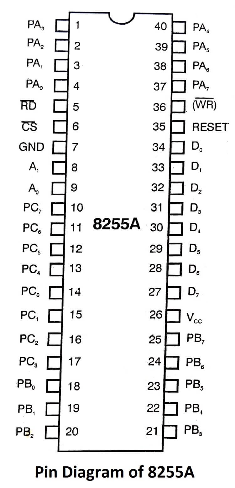
- Available in 40-Pin DIP and 44-Pin PLCC.
Pin Diagram of 8255A

| Read More Topics |
| Communication Between 8086 and 8089 |
| Multiprocessor configuration of 8086 |
| Serial communication programming |


