Multiprocessor Configurations
A multiprocessor system will have two or more processors that can execute instructions or perform operations simultaneously.
Need for Multiprocessor System
Due to limited data width and lack of floating point arithmetic instructions, 8086 requires many instructions for computing even single floating point operation. For this Numeric Data Processor.
Some processor like DMA controllers can help 8086 with level operations, while the CPU can take of the high level operations.
Advantages :
Several low cost processors may be combined to fit the needs of an application while avoiding the expense of the unneeded capabilities of a centralized system.
It is easy to add more processor for explasion as per requirement.
When a failure occurs, it is easier to replace the faulty processor.
In a multiprocessor system implementation of modular processing of task can be achived.
Basic Multiprocessor Configurations
- Co processor configuration
- Closely coupled configuration
- Loosely coupled configuration
Coprocessor Configuration
In coprocessor configuration both the CPU (8086) and external processor (math Co-processor 8087) share entire memory input and output sub system.
They also share same bus control logic and clock generator. 8086 is the master and 8087 is the slave.
Coprocessors add instructions to the instruction set. An instruction to e executed by the coprocessor is indicated by an escape (ESC) prefix or instruction.
- The 8086 fetches the instructions.
- The coprocessor monitors the instruction sequence and captures its own instructions.
- The ESC is decoded by the CPU and coprocessor simultaneously.
- The CPU computes the 20 bit adders of memory operand and does a dummy read. The coprocessor captures the address of the data and obtains control of the bus to load or store as needed.
- The coprocessor sends BUSY (high) to the TEST pin.
- The CPU goes to the next instruction and if this is an 8086 instruction, the CPU and coprocessor executed in parallel.
- If another coprocessor instruction occurs, the 8086 must wait until BUSY goes low, TEST pin become active. To implement this, a WAIT instruction is put in front of most 8087 instructions by the Assembler.
- The WAIT instruction does the operations, wait until the TEST pin is active.
- The coprocessor also makes use of Queue Status (QS – QS) of the 8086 instructions queue.
Closely Coupled Configuration
Coprocessor and closely coupled configurations are similar in that both the 8086 and the external processor 8089
-
-
- Memory
- I/O system
- Bus and Bus control logic
- Clock generator
-
The main difference between coprocessor and closely coupled configuration is, no special instruction WAIT or ESC is used. The communication between 8086 and independent processor is done through memory space.
The 8086 sets up a message in memory and wakes up independent processor by sending command to one of its ports.
The independent processor then accesses the memory to execute the task in parallel with 8086. When task is completed the external processor informs the 8086 about the completion of task by using either a status bit or an interrupt request.
Loosely Coupled Configuration
In loosely coupled configuration a number of modules of 8086 can be interfaced through a common system bus to work as a multiprocessor system.
Each module in the loosely coupled configuration is an independent microprocessor based system with its own clock source, its own memory input and output devices interfaced through a local bus.
Each module can also closely coupled configuration of a processor or coprocessor.
Advantages
- Better system throughput by having more than one processor.
- The system can be expanded in modular form. Each processor is an independent union and normally on a separate PC board. One can be added or removed without affecting the other in the system.
- A failure in one module normally does not affect the breakdown of the entire system and fault module can be easily detected and replaced.
Daisy Chaining
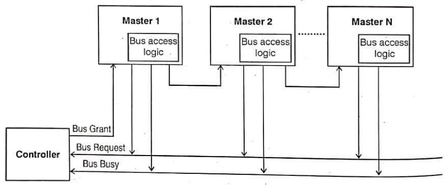
In daisy chaining method all masters make use of the same line for bus request. In response to a bus request, the controller sends a bus grant if the bus if free.
The bus grant signal serially propagates through each master until it encounters the first one that is requesting access to the bus.
This master blocks the propagation of the bus grant signal, activates the busy line and gains control of the bus. Therefore any other requesting module will not receive the grant signal and hence cannot get the bus access.
This bus allocation scheme is simple and cheaper. But failure of any one master causes the whole system to fail and arbitration is slow due to the propagation delay of bus grant signal is proportional to the number of masters. The connection diagram for daisy chaining method.

Polling Method
In polling method, the controller sends address of device to grant bus access. The number of address lines required is depend on the number of masters connected in the system.
For example, if three master are connected in the system, one address line required. In response to a bus request, controller generates a sequence of master addresses.
When the requesting master recognizes the address, it activates the busy line and begins to use the bus.
The priority can be changed by altering the polling sequence stored in the controller. Another one advantage of this method is, if one module fails entire system not fail.
8086 microprocessor is basically an integer processing unit and works directly on variety of integer data types.
Most of the programs used in engineering, science, business need of an angle etc. But it may be needed to perform are no instructions with very large number like ten power +71 or very small number.
There are no instructions in 8086 to directly find sine of an angle etc. Also 8086 can only perform computations on 16 bit fixed point numbers with a range of 32768 to + 32767. To solve this numeric data processor is used to solve many useful functions like square root, exponential, tangent, logarithm.
Features of 8087 – Multiprocessor
- 8087 is a high performance data co-processor.
- It adds arithmetic, trigonometric, exponential and logarithmic instructions to 8086/8088 instruction set for all data types.
- It supports 16,32,64-bit integers, 32,64, 80 bits floating point and 16 digit BCD data types.
- Compatible with IEEE floating point standard.
- It adds 8 × 80 bit individually addressable register stack to the 8086/8088 architecture.
- It has a built in exception handling functions.
- Multi bus system compatible interface.
- It is designed to specially work with 8086 and 8088 processors.
- Fabricated to specially work with 8086 and 8088 processors.
- It is fabricated using HMOS-III technology and packed in a 40 pin CERDIP.
- It has 6 group of instructions : Data transfer instructions, Arithmetic instructions, Compare instructions, Transendental instructions, Load constant instructions and processor control instructions.
Architecture of 8087 – Multiprocessor
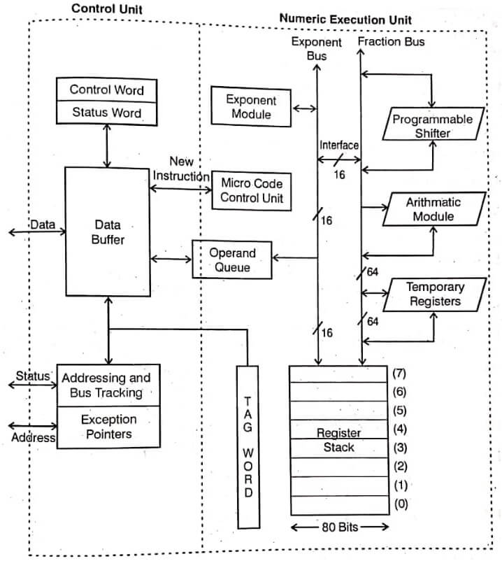
The internal architecture of 8087 is shown before image. The 8087 is divided into two functional units control unit (CU) and Numeric Execution Unit (NEU).
The executes all the numeric processor instructions while the CU receives, decodes, instructions, reads and writes memory operands and executes the 8087 control instructions. These two units may work asynchronously with each other.

Control Unit
The numeric data processor data address and status lines are directly connected to the corresponding 8086 main processor’s data, address and status lines respectively that facilitates the 8087 to keep track decode the instructions fetched by 8086. The functional parts of the control unit are,
- Control word register
- Status word register
- Data buffer
- Shared operands queue
- Addressing and bus tracking
- Exception pointers
The control unit is mainly responsible for establishing communication between the CPU and memory and also for coordinating the internal coprocessor execution.
The CPU, while fetching the instructions from memory, monitors the data bus to check for the 8087 instructions. Meanwhile, 8087 control unit internally maintically monitors the BHE S7 line to detect the CPU type, 8087 further uses the QS pins to obtain and identify the instructions fetched by the host CPU.
Which identifies the coprocessor instructions using the ESCAPE code bits in them. Once the CPU recognizes the ESCAPE code, it triggers the execution of the numeric processor instruction 8087.
If the instruction is an ESCAPE instructions, the coprocessor executed it and it not, the microprocessor executes it.
8089 I/O Processor – Multiprocessor
8089 is an input and output processor (IOP) is used to take care of all the system input – output activities. Once initiated by the host CPU, the IOP receives requests from the system peripherals, it issues commands to the system peripherals and also keeps track of the operation of the peripherals.
When it completes the task, it either interputs the CPU or maintains a busy flag in the memory based table, which is periodically checked by the host CPU. The 8089 may be operated in tightly coupled or loosely coupled configurations.

Communication Between 8086 and 8089
The IOP is similar to a CPU except it is designed to handles the details of I/O processing, Unlike the DMA controller that must be set up entirely by the CPU, the IOP can fetch and execute its own instructions.
IOP instructions are specifically designed to facilitate I/O transfers. In addition, the IOP can perform other processing asks, such as arithmetic, logic, branching, and code translation.
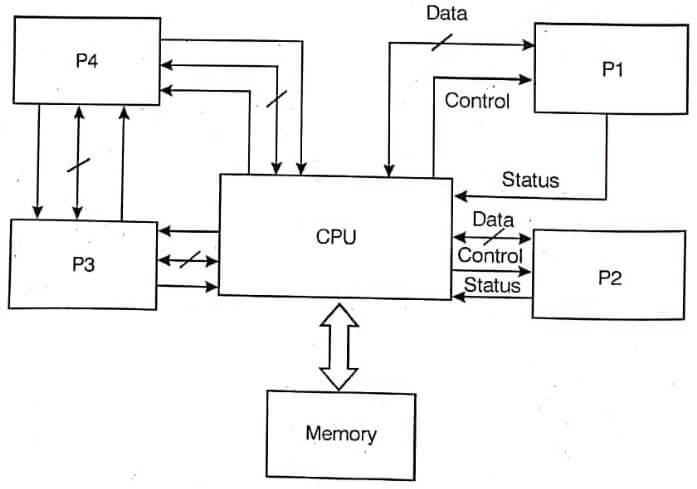
The block diagram of a computer with two processors is shown in image. The memory unit occupies a central position and can communicate with each processor by means of direct memory access.
The CPU is responsible for processing data needed in the solution of computation tasks. The IOP provides a path for transfer data between various peripheral devices and the memory unit. The CPU is usually assigned the task of initiating the I/O program.
The communication between the IOP and devices attached to it is similar to the program control method of transfer. Communication with memory is similar to the direct memory access method.
The way by which CPU and IOP communicate depends on the level of sophistication included in the system. In very large scale computers each processor is independent of all other and anyone processor can initiate an operation.
| Read More Topics |
| Microprocessor Based Controller |
| Instruction set architecture of 8051 |
| 8086 Microprocess Intel Software Aspects |
| Evaluation of Microprocessor 8085 |
| Microcontroller 8051 I/O and Timer Bit |


