Micro-hydro, defined as a plant between 10kW and 200kW, is perhaps the most mature of the modern small-scale decentralised energy supply technologies used in developing countries. Micro hydro power plant is energy from water sources such as the ocean, rivers and waterfalls.
“Micro-hydro” means which can apply to sites ranging from a tiny scheme to electrify a single home, to a few hundred kilowatts for selling into the National Grid. Micro-hydropower is one of the most cost-effective and reliable energy technologies to be considered for providing clean electricity generation. Water can be harnessed on a large or a small scale. Table 1 below outlines the categories used to define the power output form hydropower.
Classification of hydro-power by size
Over the last few decades, there has been a growing realisation in developing countries that micro-hydro schemes have an important role to play in the economic development of remote rural areas, especially
mountainous ones. Micro-hydro schemes can provide power for industrial, agricultural and domestic uses through direct mechanical power or by the coupling of the turbine to a generator to produce electricity.
Components of Micro-Hydro Power Plant
Main components of a Micro-hydro power plant can be summarized as follows:
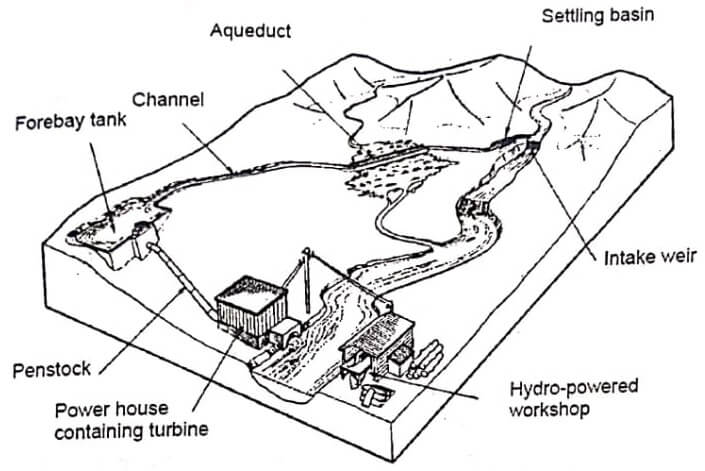
- Water is taken from the river by diverting it through an intake at a weir.
- In medium or high-head installations, water may first be carried horizontally to the forebay tank by small canal.
- Before descending to the turbine, the water passes through a settling tank or ‘forebay’ in which the water is slowed down sufficiently for suspended particles to settle out.
- Forebay is usually protected by a rack of metal bars (a trash rack) which filters out waterborne debris.
- A pressure pipe, or ‘penstock’, conveys the water from the forebay to the turbine, which is enclosed in the power house together with the generator and control equipment.
- After leaving the turbine, the water discharges down a ‘tailrace’ canal back into the river.
Fig shows the main components of a run-of-the-river micro- hydro scheme. This type of scheme requires no water storage but instead diverts some of the water from the river, which is channeled along the side of a valley before being ‘dropped’ into the turbine via a penstock. In fig, the turbine drives a generator that provides electricity for a workshop. The transmission line can be extended to a local village to supply domestic power for lighting and other uses.
There are various other configurations which can be used depending on the topographical and hydrological conditions, but all adopt the same general principle.
Power from a Micro-Hydro Plant
The energy associated with water manifests itself in three ways: as potential energy, pressure energy, and kinetic energy. The energy in an hydroelectric system starts out as potential energy by virtue of its height above some reference level. In this case, the height above the power house produces potential energy. Water under pressure in the penstock is able to do work when released, so there is energy associated with that pressure as well. Finally, as water flows, there is the kinetic energy that associated with any mass that is moving.
It is convenient to express each of these three forms of energy on per unit of weight basis, in which case energy is referred to as head in metres. Total energy is the sum of the potential, pressure and kinetic energy and is given by
Where, z = elevation above the reference height in m
p = pressure in N/m²
ϒ = specific weight in N/m³
v = average velocity in m/s
To determine the power potential of the water flowing in a river or stream, it is necessary to determine both the flow rate of the water and the head through which the water can be made to fall. The flow rate is the quantity of water flowing past a point in a given time. Typical flow rate units are litres per second or cubic metres per second. The head is the vertical height, in metres, from the turbine up to the point where the water enters the intake pipe or penstock. The potential power can be calculated as follows:
Theoretical power (P) = Flow rate (Q) × Head (H) × Gravity (g)
Where, Q is in cubic metres per second,
H in metres, and
g = 9.81 mls² then,
P = 9.81 x Q × H (kW)
Example: A turbine generator set operating at a head of 10 metres with flow of 0.3 cubic metres per second will deliver approximately, (9.81 x 0.5 x 0.3 x 10 =) 18 kilowatts of electricity.
However, energy is always lost when it is converted from one form to another. Small water turbines rarely have efficiencies better than 80%. Power will also be lost in the pipe carrying the water to the
turbine, due to frictional losses. By careful design, this loss can be reduced to only a small percentage. A rough guide used for small systems of a few kW rating is to take the overall efficiency as approximately 50%. Thus, the theoretical power must be multiplied by 0.50 for a more realistic figure.
If a machine is operated under conditions other than full-load or full-flow, then other significant inefficiencies must be considered. Part flow and part load characteristics of the equipment need to be known to assess the performance under these conditions. It is always preferable to run all equipments at the rated design flow and load conditions, but it is not always practical or possible where river flow fluctuates throughout the year or where daily load patterns vary considerably.
Suitable Conditions for Micro-Hydro Power
The best geographical areas for exploiting small scale hydro power are those where there are steep rivers flowing all year round, for example, the hill areas of countries with high year round rainfall, or the
great mountain ranges and their foothills, like the Andes and the Himalayas. Islands with moist marine climates, such as the Caribbean Islands, the Philippines and Indonesia are also suitable. Low head
turbines have been developed for small scale exploitation of rivers where there is a small head but sufficient flow to provide adequate power.
To assess the suitability of a potential site, the hydrology of the site needs to be known and a site survey carried out, to determine actual flow and head data. Hydrological information can be obtained from the meteorology or irrigation department usually run by the national government.
This data gives a good overall picture of annual rain patterns and likely fluctuations in precipitation and, therefore, flow patterns. The site survey gives more detailed informations of the site conditions to allow power calculation to be done and design work to begin. Flow data should be gathered over period of at least one full year where possible, so as to ascertain the fluctuation in river flow over the various seasons.
Turbines for Micro Hydro Power
A turbine converts the energy in falling water into shaft power. There are various types of turbine which can be categorised in one of several ways. The choice of turbine will depend mainly on the pressure head available and the design flow for the proposed hydropower installation. As shown in table below, turbines are broadly divided into three groups; high, medium and low head, and into two categories: impulse and reaction.
Classification of turbine types
| Head Classification | |||
| Turbine type | High head (>50m) | Medium head (10-50m) | Low head (<10m) |
| Impulse | Pelton, Turgo, Multi-jet pelton | Cross flow, Turgo, Multi-jet pelton | Cross flow |
| Reaction | Francis (spiral case) | Francis (Open flume) Propeller, kaplan | |
The difference between impulse and reaction can be explained simply by stating that the impulse turbines convert the kinetic energy of a jet of water into the movement by striking turbine buckets or blades. There is no pressure reduction as the water pressure is atmospheric on both sides of the impeller. The blades of a reaction turbine, on the other hand, are totally immersed in the flow of water, and the angular as well as linear momentum of the water is converted into shaft power.
The pressure of water leaving the runner is reduced to atmospheric or lower. The best turbines can have hydraulic efficiencies in the range 80 to over 90%, although this will reduce with size. Micro-hydro systems (<100kW) tend to be 60 to 80% efficient.
- See More : Hydro electric power plant
- See More : Atomic hydrogen welding
- See More : Evaporative emission control system
- See More : Coal cleaning equipment
