One of the most important components in any optical fiber communication system is the optical fiber itself, since its transmission characteristics play a major role in determining the performance of the entire system.
Some of the questions that arise concerning optical fiber communication are
- What is the structure of an optical fiber?
- How does light propagate along a fiber?
- Of what materials are fibers made?
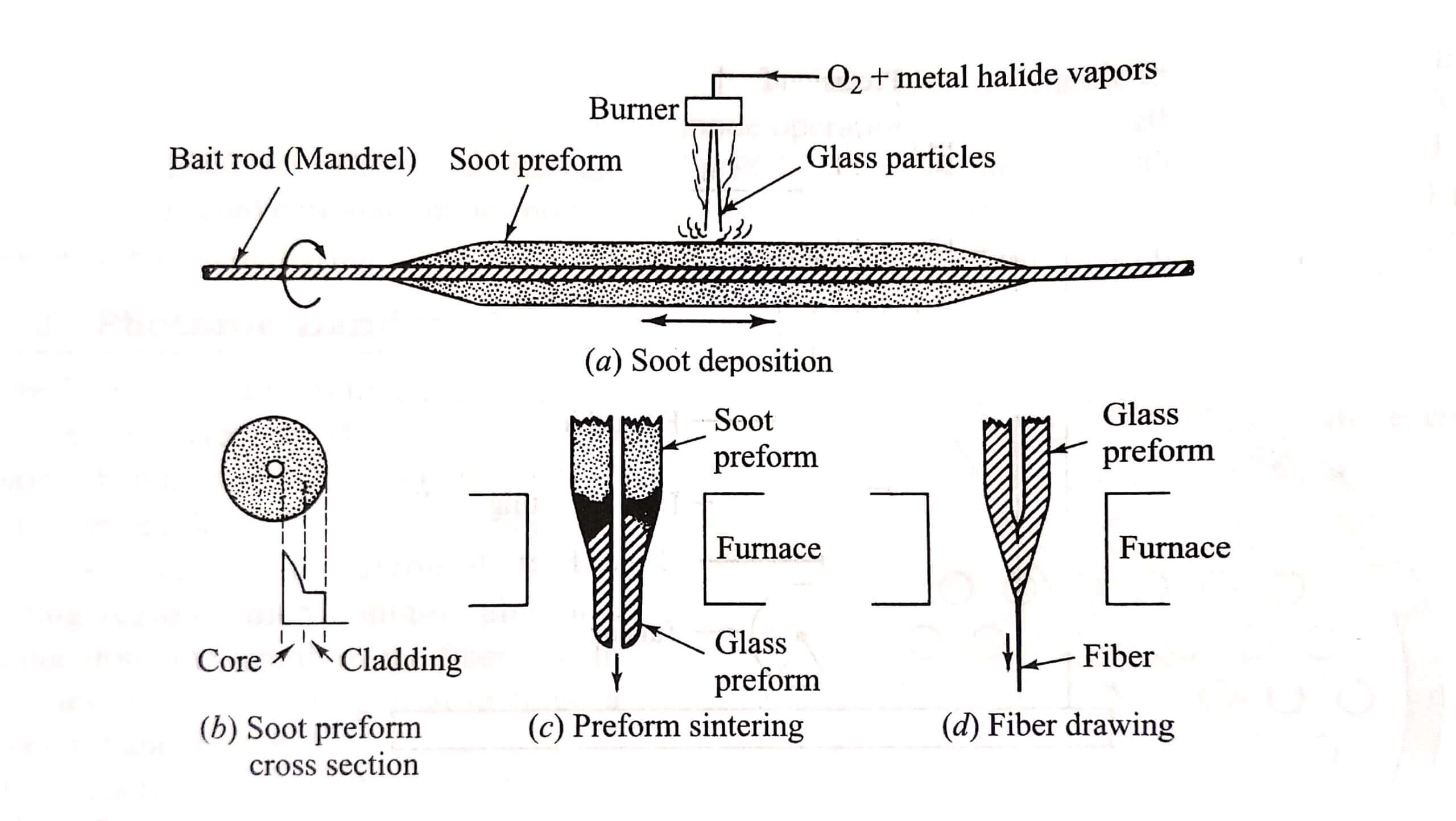
- How is the fiber fabricated?
- How are fibers incorporated into cable structures?
- What is the signal loss or attenuation mechanism in a fiber?
- Why and to what degree does a signal get distorted as it travels along a fiber?
The purpose of this chapter is to present some of the fundamental answers to the first five questions in order to attain a good understanding of the physical structure and waveguiding properties of optical fiber communication. Questions 6 and 7 are answered in Chapter 3. The discussions address both conventional silica and photonic crystal fibers.
Since fiber optics technology involves the emission, transmission and detection of light, we begin our discussion by first considering the nature of light and then we shall review a few basic laws and definitions of optics. Following a description of the structure of optical fibers, two methods are used to describe how an optical fiber guides light.
The first approach uses the geometrical or ray optics concept of light reflection and refraction to provide an intuitive picture of the propagation mechanisms. In the second approach, light is treated as an electromagnetic wave which propagates along the optical fiber waveguide. This involves solving Maxwell’s equations subject to the cylindrical boundary conditions of the optical fiber communication.
The Nature of Light – Optical Fiber Communication
The concepts concerning the nature of light have undergone several variations during the history of physics. Until the early seventeenth century, it was generally believed that light consisted of a stream of minute particles that were emitted by luminous sources. These particles were pictured as travelling in straight lines, and it was assumed that they could penetrate transparent materials but were reflected from opaque ones. This theory adequately described certain large-scale optical effects, such as reflection and refraction, but failed to explain finer-scale phenomena, such as interference and diffraction.
The correct explanation of diffraction was given by Fresnel in 1815. Fresnel showed that the approximately rectilinear propagation character of light could be interpreted on the assumption that light is a wave motion, and that the diffraction fringes could thus be accounted for in detail. Later, the work of Maxwell in 1864 theorized that light waves must be electromagnetic in nature. Furthermore, observation of polarization effects indicated that light waves are transvers (i.e., the wave motion is perpendicular to the direction in which the wave travels).
In this wave or physical optics viewpoint, the electromagnetic waves radiated by a small optical source can be represented by a train of spherical wave fronts with the source at the center. A wave front is defined as the locus of all points in the wave train which have the same phase. Generally, one draws wave fronts passing through either the maxima or the minima of the wave, such as the peak or trough of a sine wave, for example. Thus, the wave fronts (also called phase fronts) are separated by one wavelength.
When the wavelength of the light is much smaller than the object (or opening) which it encounters, the wave fronts appear as straight lines to this object or opening. In this case, the light wave can be represented as a plane wave, and its direction of travel can be indicated by a light ray which is drawn perpendicular to the phase front. The light-ray concept allows large-scale optical effects such as reflection referred to as ray or geometrical optics. The concept of light rays is very useful because the rays show the direction of energy flow in the light beam.

Linear Polarization
The electric or magnetic field of a train of plane linearly polarized waves traveling in a direction k can be represented in the general form
A(x,t) = ei Ao exp[j (ωt – k.x)]
With x=xex+yey+zezrepresenting a general position vector and k = kxex+kyey+kzez representing the wave propagation vector.
Here, A0 is the maximum amplitude of the wave, ω=2πv, where v is the frequency of the light, the magnitude of the wavevector k is k = 2π/λ, which is known as the wave propagation constant, with λ being the wavelength of the light; and ei is a unit vector lying parallel to an axis designated by i.
Note that the components of the actual (measurable) electromagnetic fields represented by are obtained by taking the real part of the equation. For example, if K=kez, and if A denotes the electric field E with the coordinate axes chosen such that ei=ex, then the real measurable electric field is given by
Ez(z,t)= Re(E) = exE0xcos (ωt – kz)
Which represents a plane wave that varies harmonically as it travels in the z direction. The reason for using the exponential form is that it is more easily handled mathematically than equivalent expressions given in terms of sine and cosine. In addition, the rationale for using harmonic functions is that any waveform can be expressed in terms of sinusoidal waves using Fourier techniques.
The electric and magnetic field distributions in a train of plane electromagnetic waves at a given instant in time. The waves are moving in the direction indicated by the vector k. Based on Maxwell’s equations, it can be shown that E and H are both perpendicular to the direction of propagation. This condition defines a plane wave, that is, the vibrations in the electric field are parallel to each other at all points in the wave. Thus, the electric field forms a plane called the plane of vibration. Likewise all points in the magnetic field component of the wave lie in another plane of vibration. Furthermore, E and H are mutually perpendicular, so that E,H, and K form a set of orthogonal vectors.
The plane wave example has its electric field vector always pointing in the ex. A general state of polarization is described by considering another linearly polarized wave which is independent of the first wave and orthogonal to it. Let this wave be
Ey(z,t) = eyE0y cos (ωt-kz+⨜)
Where ⨜is the relative phase difference between the waves. The resultant wave is
E(z,t)= Ex(z,t) + Ey(z,t)
If ⨜is zero or an integer multiple of 2π, the waves are in phase. Equation is then also a linearly polarized wave with a polarized vector making an angle
Θ = arctan E0y/E0x
With respect to ex and having a magnitude
E = (E0x2+ E0y2)1/2
This case is shown schematically. Conversely, just as any two orthogonal plane waves can be combined into a linearly polarized wave, an arbitrary linearly polarized wave can be resolved into two independent orthogonal plan waves that are in phase.
Elliptical and Circular Polarization
For general values of the wave is elliptically polarized. The resultant field vector E will both rotate and change its magnitude as a function of the angular frequency ω. We can show that for a general value of δ.
Which is the general equation of an ellipse. Thus, the endpoint of E will trace out an ellipse at a given point in space. The axis of the ellipse makes an angle αrelative to the x axis given by
To get a better picture of , let us align the principal axis of the ellipse with the x axis. Then α=0, or equivalently, δ=±π/2,±3π/2,…, so that becomes
This is the familiar equation of an ellipse with the origin at the center and semi-axes E0xand E0y,
When E0x=E0yand the relative phase difference δ=±π/2+2mπ, where m=0,±1,±2,…, then we circularly polarized light. In this case equ.
Which defines a circle. Choosing the positive sign for δ,Eqs (2.2) and (2.3) become
Ex(z,t)=exE0cos(ωt-kz)
Ey(z,t)=exE0sin(ωt-kz)
In this case, the endpoint of E will trace out a circle at a given point in space, illustrates. To see this, consider an observer located at some arbitrary point zref. Thus, as the wave moves toward the observer with increasing time, the resultant electric field vector E rotates clockwise at an angular frequency ω. It makes one complete rotation as the wave advances through one wavelength. Such a light wave is right circularly polarized.
If we choose the negative sign for δ, then the electric field vector is given by
E= E0(excos(ωt-kz)+eysin(ωt-kz)
Now E rotates counterclockwise and the wave is left circularly polarized.
The Quantum Nature of Light – Optical Fiber Communication
The wave theory of light adequately accounts for all phenomena involving the transmission of light. However, in dealing with the interaction of light and matte, such as occurs in dispersion and in the emission and absorption of light, neither the particle theory nor the wave theory of light is appropriate. Instead, we must turn to quantum theory, which indicates that optical radiation has particle as well as wave properties. The particle nature arise from the observation that light energy is always emitted or absorbed in discrete units called quanta or photons. In all experiments used to show the existence of photons, the photon energy is found to depend only on the frequency v. This frequency, in turn, must be measured by observing a wave property of light.
The relationship between the energy E and the frequency v of a photon is given by
E=hv
Where h=6.625 X 10⁻³⁴J.s is Planck’s constant. When light is incident on an atom, a photon can transfer its energy to an electron within this atom, thereby exciting it to a higher energy level. In this process either all or none of the photon energy is imparted to the electron. The energy absorbed by the electron must be exactly equal to that required to excite the electron to a higher energy level. Conversely, an electron in an excited state can drop to a lower state separated from it by an energy hv by emitting a photon of exactly this energy.
Basic Optical Laws and Definitions
This section reviews some of the basic optics laws and definitions relevant to optical fiber transmission technology. These include Snell’s law, the definition of the refractive index of a material, and the concepts of reflection, refraction, and polarization.
Refractive Index
A fundamental optical parameter of a material is the refractive index (or index of refractive). In free space a light wave travels at a speed c=3 x 10⁸ m/s. The speed of light is related to the frequency V and the wavelength λ by c=vλ. Upon entering a dielectric or non-conducting medium the wave now travels at a speed v, which is characteristic of the material and is less than c. The ratio of the speed of light in a vacuum to that in matter is the index of refraction n of the material and is given by
Typical values of n are 1.00 for air, 1.33 for water, 1.45 for silica glass, and 2.42 for diamond.
Reflection and Refraction
The concepts of reflection and refraction can be interpreted most easily by considering the behavior of light rays associated with plane waves traveling in a dielectric material. When a light ray encounters a boundary separating two different media, part of the ray is reflected back into the first medium and the remainder is bent (or refracted) as it enters the second material. This is where n2 <n1. The bending or refraction of the light ray at the interface is a result of the difference in the speed of light in two materials that have different refractive indices. The relationship at the interface is known as Snell’s law and is given by
n1 sin φ1=n2 sin φ2
or, equivalently, as
n1 cos θ1=n2 cos θ2
where the angles are defined. The angle φ1 between the incident ray and the normal to the surface is known as the angle of incidence.
According to the law of reflection, the angle θ1 at which the incident ray strikes the interface is exactly equal to the angle that the reflected ray makes with the same interface. In addition, the incident ray, the normal to the interface, and the reflected ray all lie in the same plane, which is perpendicular to the interface plane between the two materials. This plane is called the plane of incidence. When light traveling in a certain medium is reflected off an optically denser material (one with a higher refractive index), the process is referred to as external reflection. Conversely, the reflection of light off of less optically dense material (such as light traveling in glass being reflected at a glass-air interface) is called internal reflection.
Optical Fiber Modes and Configurations
Before going into details on optical fiber characteristics, this section first presents a brief overview of the underlying concepts of optical fiber modes and optical fiber configurations. The discussions in Sec 2.3 through 2.7 address conventional optical fibers, which consist of solid dielectric structures. Section 2.8 describes the structure of photonic crystal fibers, which can be created to have a variety of internal microstructures.
Fiber Types
An optical fiber is a dielectric waveguide that operates at optical frequencies. This fiber waveguide is normally cylindrical in form. It confines electromagnetic energy in the form of light to within its surfaces and guides the light in a direction parallel to its axis. The transmission properties of an optical waveguide are dictated by its structural characteristics, which have a major effect in determining how an optical fiber communication signal is affected as it propagates along the fiber. The structure basically establishes the information carrying capacity of the fiber and also influences the response of the waveguide to environmental perturbations.
The propagation of light along a waveguide can be describe in terms of a set guided electromagnetic waves called the modes of the waveguide. These guided modes are referred to as the bound or trapped modes of the waveguide. Each guided mode is a pattern of electric and magnetic field distributions that is repeated along the fiber at equal intervals. Only a certain discrete number of modes are capable of propagating along the guide. As will be seen in Sec.2.4, these modes are those modes are those electromagnetic waves that satisfy the homogeneous wave equation in the fiber and the boundary condition at the waveguide surfaces.
Although many different configuration of the optical waveguide have been discussed in the literature,3 the most widely accepted structure is the single solid dielectric cylinder of the radius a and index of refraction n1. This cylinder is known as the core of the fiber. The core is surrounded by a solid dielectric cladding which has a refractive index n2 that is less than n1. Although, in principle, a cladding is not necessary for light to propagate along the core of the fiber, it serves several purposes. The cladding reduces scattering loss that results from dielectric discontinuities at the core surface, it adds mechanical strength to the fiber, and it protects the core from absorbing surface contaminants with which it could come in contact.
In standards optical fibers the core material is highly pure silica glass (SiO2) and is surrounded by a glass cladding. Higher-loss plastic-core fibers with plastic claddings are also widely in use. In addition, most fibers are encapsulated in an elastic, abrasion-resistant plastic material. This material adds further strength to the fiber and mechanically isolates or buffers the fibers from small geometrical irregularities, distortions, or roughnesses of adjacent surfaces. These perturbutions could otherwise cause scattering losses induced by random microscopic bends that can arise when the fibers are incorporated into cables or supported by other structures.
Variations in the material composition of the core give rise to the two commonly used fiber types. In the first case, the refractive index of the core is uniform throughout and undergoes an abrupt change (or step) at the cladding boundary. This is called a step-index fiber. In the second case, the core refractive index is made to vary as a function of the radial distances from the center of the fiber. This type is a graded-index fiber.
Both the step and the graded-indexs fibers can be further divided into single- mode and multimode classes. As the name implies, a single-mode fiber sustains only one mode of propagation, whereas multimode fibers contain many hundreds of modes. A few typical sizes of single- and multimode fibers to provide an idea of the dimensional scale.
Multimode fibers offer several advantages compared with single-mode fibers. As we shall see in Chapter 5, the larger core radii of multimode fibers make it easier to launch optical power into the fiber and facilitate the connecting together of similar fibers. Another advantage is that light can be launched into a multimode fiber using a light-emitting-diode(LED) source whereas single-mode fibers must generally be excited with laser diodes. Although LEDs have less optical output power than laser diodes (as we shall discuss in Chapter 4), they are easier to make, are less expensive, require less complex circuitry, and have longer lifetimes than laser diodes, thus making them more desirable in certain applications

A disadvantage of multimode fibers is that they suffer from intermodal dispersion. We shall describe this effect in detail in Chapter 3. Briefly, intermodal dispersion can be described as follows. When an optical pulse is launched into a fiber, the optical power in the pulse is distributed over all (or most) of the modes of the fiber. Each of the modes that can propagate in a multimode fiber travels at a slightly different velocity. This means that the modes in a given optical pulse arrive at the fiber end at slightly different times, thus causing the pulse to spread out in time as it travels along the fiber.
This effect, which is known as intermodal dispersion or intermodal distortion, can be reduced by using a graded index profile in a fiber core. This allows graded-index fibers to have much larger bandwidths (data rate transmission capabilities) then step-index fibers. Even higher band-widths are possible in single-mode fibers, where intermodal dispersion effects are not present.
Rays and Modes – optical fiber communication
The electromagnetic light field that is guided along an optical fiber can be represented by a superposition of bound or trapped modes. Each of these guided modes consists of a set of simple electromagnetic field configurations. For monochromatic light fields of radian frequency ω, a mode traveling in the positive z direction (i.e., along the fiber axis) has a time and z dependence given by
The factor βis the z component of the wave propagation constant k=2π/λ and is the main parameter of interest in describing fiber in describing fiber modes. For guided modes, β can assume only certain discrete values, which are determined from the requirement that the mode field must satisfy Maxwell’s equations and the electric and magnetic field boundary conditions at the core-cladding interface.
Another method for the theoretically studying the propagation characteristics of light in an optical the light acceptance and guiding properties of optical fibers when the ratio of the fiber radius to the wavelength is large. This is known as the small-wavelength limit. Although the ray approach is strictly valid only in the zero-wavelength limit, it is still relatively accurate and extremely valuable for nonzero wavelengths when the number of guided modes is large, that is, for multimode optical fiber communication. The advantage of the ray approach is that, compared with the exact electromagnetic wave (modal) analysis, it gives a more direct physical interpretation of the light propagation characteristics in an optical fiber communication.
Since the concept of a light ray is very different from that of a mode, let us see qualitatively what the relationship is between them. (The mathematical details of the relationship are beyond the scope of this book but can be found in the literature.4-6) A guided mode traveling in the z direction (along the fiber axis) can be decomposed into a family of superimposed plane waves that collectively form a standing-wave pattern in the direction transverse to the fiber axis. That is, the phases of the plane waves are such that the envelope of the collective set of waves remains stationary.
Since with any plane wave we can associate a light ray that is perpendicular to the pulse front of the wave, the family of plane waves corresponding to a particular mode forms a set of rays called a ray congruence. Each ray of this particular number M of discrete guided modes exist in a fiber, the possible angles of the ray congruences corresponding to these modes are also limited to the same number M. Although a simple ray picture appears to allow rays at any angle greater than the critical angle to propagate in a fiber, the allowable quantized propagation angles result when the phase condition for standing waves is introduced into the ray picture. This is discussed further.
Despite the usefulness of the approximate geometrical optics method, a number of limitations and discrepancies exist between it and the exact modal analysis. An important case is the analysis of single-mode or few-mode fibers, which must be dealt with by using electromagnetic theory. Problems involving coherence or interference phenomena must also be solved with an electromagnetic approach. In addition, a modal analysis is necessary when a knowledge of the field distribution of individual modes is required. This arises, for example, when analyzing the excitation of an individual mode or when analyzing the coupling of power between modes at waveguide imperfections.
Another discrepancy between the ray optics approach and the modal analysis occurs when an optical fiber is uniformly bent with a constant radius of curvature. wave optics correctly predicts that every mode of the curved fiber experiences some radiation loss. Ray optics, on the other hand, erroneously predicts that some ray congruences can undergo total internal reflection at the curve and, consequently, can remain guided without loss.
Step-Index Fiber Structure
We begin our discussion of light propagation in an optical waveguide by considering the step-index fiber. In practical step-index fibers the core of radius a has a refractive index n1 which is typically equal to 1.48. This is surrounded by a cladding of slightly lower index n2, where
n2=n1(1-Δ)………(2.20)
The parameter Δ is called the core-cladding index difference or simply the index difference. Values of n n2 are chosen such that Δ is nominally 0.01. Typical values range from 1 to 3 percent for multimode fibers and from 0.2 to 1.0 percent for single-mode fibers. Since the core refractive index is larger than the cladding index, electromagnetic energy at optical frequencies is made to propagate along the fiber waveguide through internal reflection at the core cladding interface.
Ray Optics Representation
Since the core size of multimode fibers is much larger than the wavelength of the light we are interested in (which is approximately 1µm), an intuitive picture of the propagation mechanism in an ideal multimode step-index optical waveguide is most easily seen by a simple ray (geometrical) optics representation.6-11 For simplicity, in this analysis we shall consider only a particular ray belonging to aray congruence which represents a optical fiber communication mode.
The two types of rays that can propagate in a optical fiber communication are meridional rays and skew rays. Meridional rays are confined to the merrdian planes of the fiber, which are the planes that contain the axis of symmetry of the fiber (the core axis). Since a given meridional ray lies in a single plane, its path is easy to track as it travels along the fiber. Meridional rays can be divided into two general classesL: bound rays that are trapped in the core and propagate along the fiber axis according to the laws of geometrical optics, and unbound rays that are refracted out of the fiber core.
Skew rays are not confined to a single plane, but instead tend to follow a helical-type path along the fiber. These rays are more difficult to track as they travel along the fiber, since they do not lie in a single plane. Although skew rays constitute a major portion of the total number of guided rays, their analysis is not necessary to obtain a general picture of rays propagating in a fiber. The examination of meridional rays will suffice for this purpose. However, a detailed inclusion of skew rays will change such expressions as the light-acceptance ability of the fiber and power losses of light traveling along a waveguide.6.10
A greater power loss arises when skew rays are included in the analysis, since many of the skew rays that geometric optics predicts to be trapped in the fiber are actually leaky rays.5,12,13 These leaky rays are only partially confined to the core of the circular optical fiber communication and attenuate as the light travels along the optinal waveguide. This partial reflection of leaky rays cannot be described by pure ray theory alone. Instead, the analysis of radiation loss arising form these types of rays must be described by mode theory.
The meridional ray is for step-index fiber. The light ray enters the fiber core from a medium of refractive index n at an angle θ0 with respect to the fiber axis and strikes the core-cladding interface at a normal angle φ. If it strikes this interface at such an angle that it is totally internally reflected, then the meridional ray follows a zigzag path along the fiber core, passing through the axis of the guide after each reflection.
From Snell’s law, the minimum angle φc that supports total internal reflection for the meridional ray is given by
Rays striking the core-cladding interface at angles less than φc will refracSt out of the core and be lost in the cladding. By applying Snell’s law to the air-fiber face boundary, the conditions of eq.(2.21) can be related to the maximum entrance angle θ0,max through the relationship
Where θc=π/2-φc. Thus, those rays having entrance angles θ0 less than θA will be totally internally reflected at the core-cladding interface. Thus, θA defines an acceptance cone for an optical fiber.
Equation (2.22) also defines the numerical aperture (NA) of a step-index fiber for merridional rays:
The approximation on the right-hand side is valid for the typical case where Δ, as defined by Eq.(2.20), is much less than 1. Since the numerical aperture is related to the maximum acceptance angle, it is commonly used to describe the light acceptance or gathering capability of a fiber and to calculate source-to-fiber optical power coupling efficiencies. This is detailed in Chapter 5. The numerical aperture is a dimensionless quantity which is less than unity, with values normally ranging from 0.14 to 0.50.
Example 2.2 Consider a multimode silica fiber that has a core refractive index n1=1.48 and a cladding index n2=1.46.
a) From Eq. (2.21) the critical angle is given by
Φc=sin-1
b) From Eq. (2.22) the numerical aperture is NA=0.242
c) From Eq. (2.22)the acceptance angle in air.