Static characteristics
Static characteristic of an instrument are the parameters which are more or less constant or varying very slowly with time. The following characteristics are static characteristics performance terminology.
Range : Every sensor is designed to work over a specified range i.e. certain maximum and minimum values. The design ranges are usually fixed and if exceeded, result in permanent damage to or destruction of a sensor. For example, a thermocouple may have a range of -100 to 1260°C.
Span : It represents the highest possible input value which can be applied to the sensor without causing unacceptably large inaccuracy. Therefore, it is the difference between maximum and minimum values of the quantity to be measured.
Span = Maximum value of the input – Minimum value of the input
Error : Error is the difference between a measured value and the true input value.
Error = Measured value – True input value
Accuracy : A very important characteristic of a sensor is accuracy which really means inaccuracy. Inaccuracy is measured as a ratio of the highest deviation of a value represented by the sensor to the ideal value. The accuracy of a sensor is inversely proportional to error, highly accurate sensor produces low errors.
Sensitivity : Sensor sensitivity is defined as the change in output per change in input. The factor may be constant over the range of the sensor (linear), or it may vary (nonlinear).
Sensitivity=Change in output Change in output=∆θo∆θi
When an instrument consists of different elements connected in series and have static sensitivities of S1,S2, S3…., then the overall sensitivity is expressed as follows.
S1=θ1θi,S2=θ2θ1,S3=θ0θ2… Overall sensitivity, S =θ0θi=θ1θi×θ2θi×θ0θ2×…=S1×S2×S3….
Hysteresis – Terminology
Hysteresis is defined as the maximum differences in output for a given input when this value is approached from the opposite direction. It is a phenomenon which shows different outputs when loading and unloading. Simply, hysteresis means that both the loading and unloading curves do not coincide. That the deviation of unloading from loading condition due to hysteresis effect.
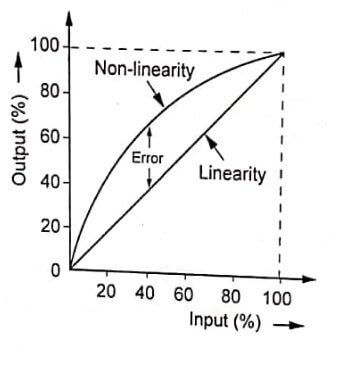
Linearity
Linearity of a sensor refers to the output that is directly proportional to input over its entire range, so that the slope of a graph of output versus input describes a straight line. If the response of the system to input A is output A, and the response to input B is output B, then the response to input C (=input A + input B) will be output C (=output A + output B).
Non-linearity
Non-linearity of a sensor refers to the output that is not proportional to input over its entire range, so that the slope of a graph of output versus input describes a curve, Non-linearity error is the deviation of output curve from a specified straight line as shown in image.
Repeatability and reproducibility
Repeatability may be defined as the ability of the sensor to give same output reading when the same input value is applied repeatedly under the same operating conditions.

Reproducibility may be defined as the degree of closeness among the repeated measurement of the output for the same value of input under the same operating conditions at different times performance terminology.
Stability
Stability means the ability of the sensor to indicate the same output over a period of time for a constant input.
Dead band/time
Dead band of a sensor is the range of input values for which the instrument does not respond. The dead band is typically a region of input close to zero at which the output remains zero.
Dead time is the time taken by the sensor from the application of input to begin its response and change.
Resolution
Resolution is defined as the smallest change that can be detected by a sensor. It can also be defined as the minimum value of the input required to cause an appreciable change or an increment in the output.
Zero Drift
Drift is the variation of change in output for a given input over a period of time. When making a measurement it is necessary to start at a known datum, and it is often convenient to adjust the output of the instrument to zero at the datum. The signal level may vary from its set zero value when the sensor works. This introduces an error into the measurement equal to the amount of variation or drift. Zero drift may result from changes of temperature, electronics stabilizing, or aging of the transducer or electronic components.
Output impedance
Impedance is the ratio of voltage and current flow for a sensor. Two types of impedance are important in sensor applications: input impedance and output impedance. Input impedance is a measure of how much current must be drawn to power a sensor. Output impedance is a measure of a sensor’s ability to provide current for the next stage of the system.
Dynamics characteristics – Performance Terminology
Sensor and actuators respond to inputs that change with time. Any system that changes with time is considered a dynamic system. Dynamic characteristics of an instrument are the parameters which are varying with time. The following characteristics are dynamic characteristics.
Response time
The time taken by a sensor to approach its true output when subjected to a step input is sometimes referred to as its response time. It is more usual, however, to quote a sensor as having a flat response between specified limits of frequency. This is known as the frequency response, and it indicates that if the sensor is subjected to sinusoidally oscillating input of constant amplitude, the output will faithfully reproduce a signal proportional to the input.
Time constant
It is the time taken by the system to reach 63.2% of its final output signal amplitude i.e., 63.3% of response time. A system having smaller time constant reaches its final output faster than the one with larger time constant. Therefore possesses higher speed of response.
Rise time
It is the time taken by the system to reach 63.2% of its final output signal.
Setting time
It is the time taken by a sensor to be within a close range of its steady state value of performance terminology.
Displacement Sensors
Displacement sensors are those sensors which measures the variation of position of a body, Displacement sensors are designed to give a quantitative measurement of the displacement being measured. Measurement of displacement is the basis of measuring position, proximity, velocity, acceleration, stress, force, pressure, thickness etc. The various displacement sensors commonly used in mechatronics systems are:
- Potentiometer displacement sensors
- Strain displacement sensors
- Capacitive displacement sensors
- Inductive displacement sensors (LVDT)
| Read More Topics |
| Tire pressure sensor work |
| Strain gauge load cell |
| Hall effect sensor work |
| Strain gauge displacement sensor |