The armature winding of an alternator is distributed over the entire armature. The distributed winding produces nearly a sine waveform and heating is more uniform. Likewise, the coils of armature winding are not full-pitched, the two sides of a coil are not at corresponding points under adjacent poles. The fractional pitched armature winding requires less copper per coil and at the same time waveform of output voltage is also improved.
Coil Span Factor or Pitch Factor
In a short pitch winding, the induced emfs in the two sides of the coil are not in phase and hence their resultant given by vector sum is always less than their arithmetic sum. The ratio of vector sum of induced e.m.f.s per coil to the arithmetic sum of induced e.m.f.s per coil is known as pitch factor (Kp) or coil span factor (Kc). It is always less than unity.
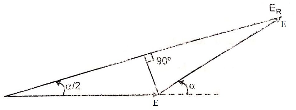
Let the coil has a pitch short by an angle α electrical space degrees from full pitch and induced emf in each coil side be E.

Now if the coil would have been full pitched, then total induced e.m.f. in the coil would have been 2E. Now when it is short pitched by α electrical space degrees the resultant induced e.m.f. Er in the coil is vector sum of two voltages at electrical angle α apart.

Hence the generated e.m.f in short pitched coil is obtained by multiplying the e.m.f generated in full pitched coils under the same conditions by cos of half of the angle by which the coil span falls short from full pitch.
Distribution or Breadth Factor
When the coils comprising a phase of the winding are distributed in two or more slots per pole, the e.m.f.s in the adjacent coils will be out of phase with respect to one another and their resultant will be less than their algebraic sum.
The ratio of the vector sum of the e.m.f.s induced in all the coils distributed in a number of slots under one pole to the arithmetic sum of the e.m.f.s induced (or to the resultant of the e.m.f.s induced in all the coils concentrated in one slot under one pole) is known as breadth factor or distribution factor (Kd).

The distribution (or breadth) factor is always less than unity
Let number of slots per pole = n
Number of slots per pole per phase = m
Induced e.m.f in each coil side = Ec
Angular displacement between the slots, β = 180°/n
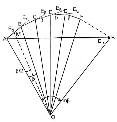
The e.m.f.s induced in different coils of one phase under one pole are represented by sides AB, BC, CD, DE, EF… which are equal in magnitude (say each equal to Ec) and differ in phase (say by β°) from each other.
If bisectors are drawn on AB, BC, CD, DE, EF… they would meet at common point say at 0. The point 0 would be the circum centre of the circle having AB, BC, CD, DE, EF,… as the coils in different slots.

E.M.F. induced in each coil side Ec = 2 AM = 2 × OA sin β/2
Arithmetic sum = m × 2 × OA sin β/2.
The resultant e.m.f induced in one polar group of one phase would be the vector sum as represented by the vector AB shown in figure.
The resultant e.m.f ![]()
![]()
Distribution factor ![]()
![]()
![]()
| Read More Topics |
| Frequency of induced emf |
| Alternator Construction and Working |
| Synchronous machines |


