Introduction to Real Power Frequency Control
Real or Active power frequency control is one of the important control actions to be performed during normal operation of the system to match the system generation with the continuously changing load, in order to maintain the constancy of system frequency to a tolerable limit of ±5%.
A change in system lead causes a change in the speed of all Turbine generator system, loading to change in system frequency.
Primary Control: The speed change from synchronous speed initiates the governor control action resulting in all the participating generator turbine units taking up the change in load, and stabilizes the system frequency.
Secondary Control: It adjusts the load references set points of selected turbine generator units so as to give nominal value of frequency.
The frequency control is a matter of speed control of the machines in the generating stations. The frequency of a power system is dependent entirely upon the speed at which the generators are rotated by their prime movers. All prime movers, whether they are steam or hydraulic turbines, are equipped with speed governors which are purely mechanical speed sensitive devices, to adjust the gate or control valve opening for constant speed.
We know N =120f
N α f
Where, N = Speed in rpm.
f = Frequency in Hz.
P = Number of poles.
So, the frequency of the system can be varied by the varying the speed of the turbine. Frequency is closely related to real power balance of the overall network. Under normal operating conditions, the system generations run synchronously and generate power which is drawn by all the loads and real power losses.
Power system operation at a lower frequency than the specified maximum permissible change in frequency is ±0.5 Hz affects the quality of power supply.
Thus, the function of load frequency control on a power system becomes one of changing the control valve, or gate openings of the prime movers, as a function of load variations in order to hold system frequency constant.
Let us consider the problem of controlling the power output of the generators, so as to maintain the scheduled frequency. All the generators speed up and slow down together maintaining their relative power angles, thus maintaining the frequency. Such as area is called as a control area.
Constancy speed of motor drives is particularly important for satisfactory performance of generating units, as they are dependent on performance of all the auxiliary drives associated with fuel, feed water and combustion ai4r supply system. In an interconnected system, two or more areas in addition to control of frequency, the generation within each area has to be controlled, so as to maintain scheduled power interchange.
Definitions – Power Frequency Control
- Speed-Governor : It comprises of the elements which are directly responsive to speed and whose positions influence the action of other elements of speed governing system.
- Speed-Control Mechanism : It includes all equipment like relays, pilot valve, servomotor, pressure or power amplifying devices, levers and linkages existing between the speed-governor and the governor-controlled valves.
- Governor-Controlled Valves: This includes those valve that control the input to the turbine, and that are normally actuated by the speed governor with the help of speed control mechanism.
- Speed-Changer (or) Speeder Motor: It is a devices by means of which the speed governing system may be adjusted to change the speed or power output of the turbine in operation.
- Speed-Governing System: This includes the speed governor, speed control mechanism, governor-controlled valves and speed changes.
Fundamentals of Speed Governing Mechanism and Modelling
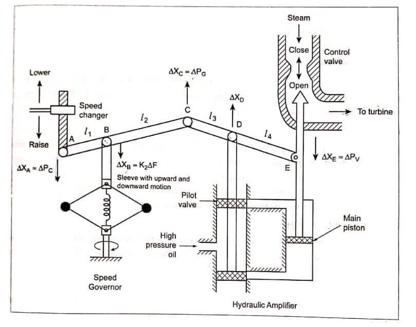
The real power is a power system is being controlled by controlling the driving torques of the individual turbines of the system. The speed governor is the main primary tool for the load frequency control, whether the machine is used alone to feed a smaller system or it is a part of the most elaborate arrangement. Schematically the speed governing system of the steam turbine. By controlling the position of the control valve or gate, we can exert control over the flow of high pressure steam (or water) through the turbine.
The components of speed governing systems are as follows:
Fly Ball Speed Governor
It is purely mechanical speed sensitive device coupled directly to the hydraulic amplifier, which adjusts the control valve opening via the linkage mechanism.
As the load increases, speed of the turbine decreases, and the speed changer givers raise command, so the fly balls move outwards and the point B moves downwards and the reverse happens with the increased speed.
Speed Changer
It makes it possible to restore the frequency to the initial (nominal) value after the operation of the speed governors which has steady state characteristics. A small downward movement of the linkage point A corresponds to an increase ΔP, in the reference power setting.
Hydraulic Amplifier
It consist of pilot valve and main piston. With this arrangement, a low power pilot valve movement is converted into high power level movement of the oil-servomotor piston. The input to this amplifier is the position XD of the pilot valve. The output is the position XE of the main piston. Hydraulic amplification is necessary, so that the steam valve or gate could be operated against high pressure steam.
Linkage Mechanism
ABC is a rigid link pivoted at B and CDE is another rigid link pivoted at D. The function of the link mechanism is to control the steam valve or gate. We get feedback from the movement of the steam valve via link CD.
Working
As load increases, the speed of the turbine decreases, the speed changer gives raise command and the fly balls move outwards and the point B moves downwards and D moves upwards and high pressure oil enters into the upper pilot valve and presses the main piston downwards and opens the value or gas increases the flow of steam to the turbine. Thereby, speed of the turbine increases and maintain constant frequency.
Model of Speed Governor
We shall develop the mathematical model based on small deviations around a nominal steady state. Consider the steam is operating under steady state and is delivering power PG0 from the generator at nominal frequency f0.
Let XS0 be the steam value setting.
Let us assume that raise command ΔPC, to the speed changer, the pont A be moved downwards by a small amount ΔXA which causes the turbine power output to change.
ΔX A = kC ΔPC
Let us assume positive direction for downward movement and negative direction for upward movement.
| Read More Topics |
| Directional control valve |
| Evaporative emission control system |
| Microprocessor based controllers |


