An AM wave expression consists of carrier and two sidebands. The carrier component of the modulated wave has the same amplitude as the unmodulated carrier.
The AM modulated wave contains extra power in the two sideband components. The amplitude of the sidebands depends on the modulation index ‘ma‘. Therefore the total power in the modulated wave will depend on the modulation index also.
Thus, the total power in the AM modulated wave can be expressed as,
![Rendered by QuickLaTeX.com \begin{aligned} \mathrm{P}_{\mathrm{T}} & =[\text { Carrier power }]+[\text { Power in LSB }]+[\text { Power in USB }] \\ & =\mathrm{P}_{\mathrm{C}}+\mathrm{P}_{\mathrm{LSB}}+\mathrm{P}_{\mathrm{USB}} \\ & =\frac{\mathrm{V}_c^2}{\mathrm{R}}+\frac{\mathrm{V}_{\mathrm{LSB}}^2}{\mathrm{R}}+\frac{\mathrm{V}_{\mathrm{USB}}^2}{\mathrm{R}}(\mathrm{rms}) \end{aligned}](https://pedagogyzone.com/wp-content/ql-cache/quicklatex.com-68a7f2ef8aba7e4f0f40be63a4daa39c_l3.png)
Where all three voltages are in rms values, and and R is the antenna resistance in which the power is dissipated.
CARRIER POWER (Pc)
The average power dissipated in a load by an unmodulated carrier is equal to the rms carrier voltage squared divided by the load resistance.

POWER IN THE SIDEBANDS
The upper and lower sideband powers are expressed mathematically as,

The peak voltage of the upper and lower side band frequencies are,
![]()

Where,
PUSB – Upper side band power (Watts), and
PLSB – Lower sideband power (Watts).

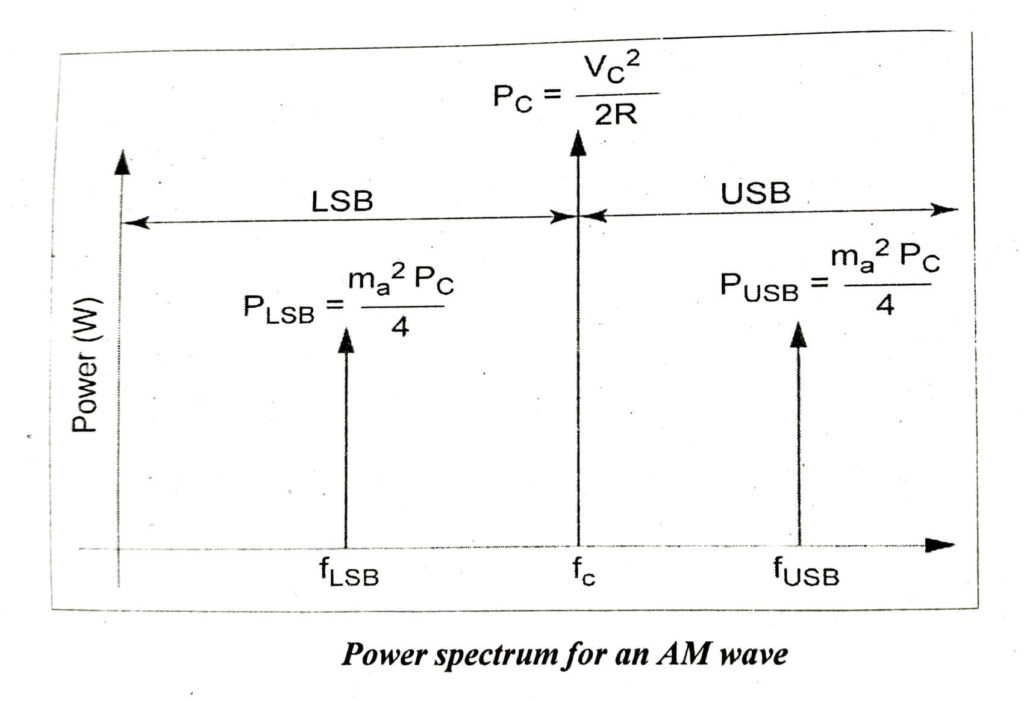
![Rendered by QuickLaTeX.com \begin{aligned} \mathrm{P}_{\mathrm{T}} & =\mathrm{P}_{\mathrm{C}}+\mathrm{P}_{\mathrm{USB}}+\mathrm{P}_{\mathrm{LSB}} \\ & =\frac{\mathrm{V}_{\mathrm{C}}^{2}}{2 \mathrm{R}}+\frac{m_{a}^{2}}{4} \frac{\mathrm{V}_{\mathrm{C}}^{2}}{2 \mathrm{R}}+\frac{m_{a}^{2}}{4} \frac{\mathrm{V}_{\mathrm{C}}^{2}}{2 \mathrm{R}} \\ & =\mathrm{P}_{\mathrm{c}}+\frac{m_{a}^{2}}{4} \mathrm{P}_{\mathrm{c}}+\frac{m_{a}^{2}}{4} \mathrm{P}_{\mathrm{c}} \\ & =\mathrm{P}_{\mathrm{c}}\left[1+\frac{m_{a}^{2}}{4}+\frac{m_{a}^{2}}{4}\right] \\ \mathrm{P}_{\mathrm{T}} & =\mathrm{P}_{\mathrm{c}}\left[1+\frac{m_{a}^{2}}{2}\right] \end{aligned}](https://pedagogyzone.com/wp-content/ql-cache/quicklatex.com-dbf43e9651e98ada79459f486cc4ec81_l3.png)
If ma = 1 for 100% modulation (VC = Vm), then

MODULATION INDEX INTERMS OF PT AND PC

