Introduction – Power System
In general, each generating plans in any power system may have more than one generating unit. Each of the unit may have identical or different capacities. A number of power plants can be tied together to supply the system load by means of interconnection of the generating stations.
Interconnected electric power system is more reliable, and convenient to operate and also offers economical operating cost. It offers better regulation characteristics, since a load change in any of the area is taken care of by all units in the interconnection. The loss of a generating unit in one of the areas can be compensated by spinning reserve to most the required load continuously.
In planning a power system, it is necessary to select suitable types of plant, and choose their sizes so that the overall cost of the energy delivered at the load centers to the consumers is minimum. Thus, the economic operation of the power system involves the selection of suitable generating unit, to satisfy the power demand for the energy supplied.
POWER SYSTEM OPERATION AND CONTROL
Automatic control systems are used extensively in power systems. Local controls are employed at turbine generator units (governor control) and at selected voltage controlled buses. Central controls are employed at area control centers.
Power system operations have the responsibility to ensure that adequate power is delivered to the load reliably and economically in order to ensure adequate delivery of power demand. The electric energy system can be operated at the desired operating level by frequency and the voltage profile and load flow configuration. The nominal frequency and the voltage profile are maintained automatically. The real and reactive powers generated are controlled automatically. In a power station, the generating electrical power unit must satisfy the load demand.
Power system control is required to maintain a continuous balance the generation and varying load demands, while system frequency, voltage levels and security are maintained within the specified limits. Operating costs vary widely among controlled units. Economic dispatch determines the megawatt output of the controlled units that minimize the total operating cost for a given load demand. Economic dispatch is coordinated with load frequency control (LFC) in such a way that reference power signals dispatched to controlled units move the units towards these economic loadings and satisfy LFC objectives.
Active power generation is normally specified according to economic dispatching practice and the generator voltage magnitude is normally maintained at a specified level by the AVR acting on the machine excitation.
Objective; To maintain a continuous balance between electrical generation and varying load demand while system frequency and voltage levels are maintained constant.
Optical power flow combines economic dispatch with power flow so as to optimize generation without exceeding limits on transmission line loadability.

Power Stations
An electric power station is a factory in which energy is converted from one form of energy into electrical energy.
Steam Plant
The generating plants, which use coal, are called thermal power plants. The coal is burnt by combustion in the boiler furnace and heat is liberated which converts water into steam. The energy in the steam is converted to the mechanical energy of a rotating shaft by some form of steam engine, either reciprocating or turbine and this energy is converted into electrical energy by means of a generator. Normally, the efficiency of this unit is very low and it will take longer time for starting the generating unit.
Hydro-Power Plant
Water is a great potential source of energy. The generating plants that obtain energy from water are called hydroelectric power plants. Potential energy of water is converted into mechanical energy in a water turbine, which drives the electrical generator.
The advantages are;
- No fuel is required
- Low maintenance costs.
- Quick start-up.
Nuclear or Atomic Station
The power obtained from nuclear fission is called nuclear power or atomic power. Power, plants using this energy are called as Nuclear power plants or Atomic power plants.
The energy from the splitting of the atomic fuel is released in the form of heat in the reactor. The materials that undergo nuclear fission are Uranium (U235), Thorium (Th232) and Plutonium (Pu239).
When 1 kg of U235 fissioned, 25×109 KWhr of heat energy can be produced. The heat obtained from the reaction is used to convert water into steam. It may be said that, basically a nuclear power plant is a thermal power plant in which nuclear reactor replaces the steam boilers.
Diesel Power Plant
Diesel engine is a prime mover that obtain its energy from a liquid fuel generally known as diesel oil and converts energy into mechanical energy. An alternator mechanically coupled to it converts the mechanical energy into electrical energy. They can be started and stopped quickly. Diesel power plants and gas turbine units are otherwise called as ‘spinning reserves’ because they can be started instantly when other generating unit fails.
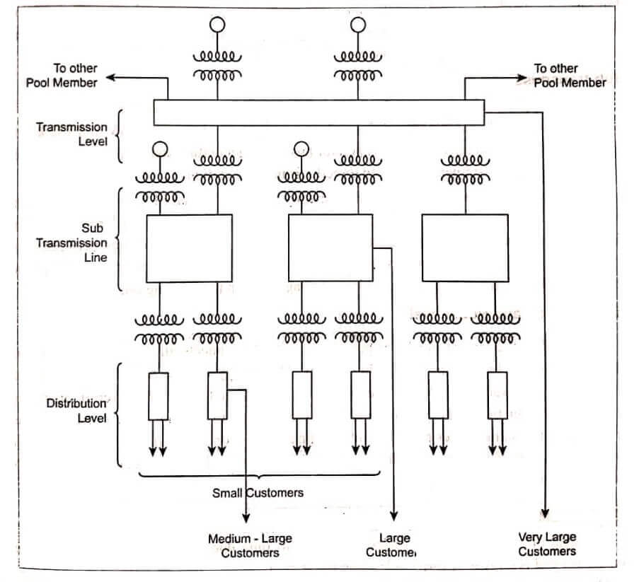
Structure of Electric Power System
Power transmittability increases and transmission losses decreases with increasing voltage level. The larger the blocks of power to be transmitted and the greater the distance over which they must be wheeled, the higher must be the operating voltage chosen.
- Distribution Level (Secondary and Primary)
- Sub-transmission level.
- Transmission and Pool Level
Distribution Level
These circuits are the finest meshes in the network. Distribution voltage levels are classified into two types.
- Primary or Feeder Voltage (For instance 33kV)
- Secondary or Consumer Voltage (For instance 230 V per phase)
The distribution circuits fed from the distribution substations supply energy to the domestic or medium sized (small industrial and commercial) customers. Distribution Engineering constitutes the major part covering the problems of overhead or underground service, metering, switching and protection.
Sub-transmission Level
The sub-transmission line distributers energy to a number of distribution substations in a certain geographical area at a voltage level that typically varies between 33kV and 132kV. It receives the energy directly from the generator bus in the generator bus in the generating station or via bulk power substations. Large customers are served directly from those stations.
The role of a sub-transmission system is mainly the same as that of a distribution system except that it serves a larger geographical area and distributes energy in larger blocks at higher voltage levels. In many systems there are no clear demarcation lines between sub-transmission and transmission systems. Increased lead density makes it necessary and economical to superimpose a new and higher voltage grid on the existing one.
Transmission and Pool Level
This handles the largest blocks of power. Also it interconnects all the generator stations and all the major loading points in the system. The energy can be routed in any desired direction on the various links of the transmission system to the best overall operating economy via inter ties. Transport of energy can take place to or from other power systems belonging to the same power pool. It tends to appear as a loop structure. So it has more path combination that better suits for the purpose of the transmission level. The depicts the above fact.
SYSTEM LOAD VARIATION
The load on a power station varies from time to time due to uncertain demands of the consumers and is known as variable load on the station.
The system load in an area depends on residential, commercial, industrial, agricultural, municipal and traction load variation occurs due to special events on religions and social occasions etc.
System load variation occurs due to weather condition (i.e) temperature, humidity, cloudiness, wind velocity etc.
Load taken by enough group, thin peaks do not occur at the same time, because of system load variation.
Residential Load; It consists of domestic lights, fans and other appliances such as heators, refrigerators, television, radio, air-conditioner, etc., has a high peak during evening.
Commercial Load; It covers officers, hospitals, hotels, shopping complex, theatres, etc., has two peaks, morning and evening.
Industrial load; It covers small and heavy industries working on shifts. So load is constant throughout the day.
Agricultural load; It occurs during the day time.
Municipal load; It consists of street-lighting water supply and damage.
Street lighting load remains constant from 6 p.m. to 6 a.m. Fill up the water tank during off-peak hours.
Effect of Variable Load;
Need of additional equipment:
Variable load on a station necessitates to have additional equipment. If the power demand on station increases, we should increase the generation by increasing the raw materials required (water, coal, gas, etc) so additional equipments are needed to adjust the rates of supply of raw material with respect to the power demand.
Increase in production cost:
Variable load on the plant increases the production cost of electrical energy. If one alternator is used to meet on the load variation, it will have poor efficiency during light load period. Therefore a number of alternators of different capacities are installed so that most of the alternators can be operated at nearly full load capacity. So, number of generators are used to meet out the load variation, increases the production cost.
SYSTEM LOAD CHARACTERISTICS
Load; Load is a device that taps energy from the network.
The load devices may vary from a few watt night lamps to multi-megawatt induction motors. The following categories of loads are in a system:
- Motor devices – 70%
- Heating and lighting equipment – 25%
- Electronic devices – 5%
The heating load maintains constant resistance with voltage change, and hence, the power varies with (voltage)2, whereas, lighting load is independent of frequency and power consumed varies as V16 rather than V2. From the electrical point of view the multitude of devices are characterized by vast differences with regard to :
- Size
- Symmetry (single or three phase).
- Load constancy (with respect to time, frequency and voltage).
- Use cycle (regular or random use).
Rules Characterizing Typical Systems Loads
- Apart from individually of random type, the lumped or composite leads as we encounter them at sub-transmission or transmission levels, are of highly predictable character.
- These lumped and composite loads vary in a predictable fashion with time.
- Although the loads are time-variant, the variations are relatively slow.
- The typical load always consumes reactive power.
- The typical load is always symmetric.
Voltage and Frequency Load Dependency
Minor changes in voltage and frequency can cause load changes of practical significance. The three important types are:
- Impedance-type loads – Lighting, heaters, ovens
- Composite loads
- Motor loads – Induction motor loads
There are two types of characteristics:
- Static characteristics.
- Dynamic characteristics.
The static characteristics is a relation between power, torque or current and the voltage (or frequency) determined at such slow variations of the operating conditions that each of its points may be considered as corresponding to a steady state.
P = P(IVI)
Q = Q(IVI)
Where P,Q,V represent the active power, reactive power and voltage respectively.
The dynamic characteristics is the same relation but defined for fast variations of the operating condition that their rate of change has to be taken into account.
Static Characteristics
Lighting and Heating Loads
The active power consumed by a heating load varies with (voltage)2 and the heating load maintains constant resistance with voltage change. Such a load consumes no reactive power.
ECONOMICS OF GENERATION – Power System
The generating stations may be steam, hydro, nuclear, diesel or any other type. This factor mainly depends upon the natural sources available in the areas. The power station should be as near as possible to the centre of the load so that the transmission cost and losses are minimum. The schemes employed should be such that extension could be made to meet with the increase in demand in future, without incurring heavy expenditure.
Load Curves:
Load on the power system is seldom constant. It varies from time to time. The curve showing the variation of load on the power station with respect to time is known as a load curve. It can be plotted on a graph taking load on Y-axis and time on X-axis.
Daily Load Curve:
The curve showing the variation of load on a whole day i.e., 24 hours with respect to time is known as daily load curve. The load variation are recorded half-hourly or hourly on a whole day (24 hrs).
Monthly Load Curve:
The curve showing the variations of lead of the month with respect to time is known as monthly load curve.
It can be obtained from the daily load curves of that month. It can be plotted by calculating the average values of power over a month at different times of the day. It is used to fix the rates of energy or tariff.
Yearly Load Curve or Annual Load Curve:
The curve showing the variation of load of the year with respect to time is known as yearly or Annual load curve.
It can be obtained from the mostly load curves of the year. It is used to determine the annual load factor.
The load curves supply the following information:
- The variation of the load during different hours of the day.
- The area under the curve represents the total number of units generated in a day.
- The peak of the curve represents the maximum demand on the station on the particular day.
- The area under the load curve represent is divided by the number of hours, gives the average load on the power station.
- The ratio of the area under the load curve to the total area of the rectangle in which it contained, gives load factor.
Load Duration Curve
This is another type of curve which indicates the variation of load, but with the loads arranged in descending order of magnitude, i.e., the greater load on the left and lesser loads towards right. From this curve, the load factor of the station can also be determined. Typical load duration curve is as shown.
Important Terms for Deciding the Type and Rating of Generating Plant
Connected Load
For deciding the type and rating of generating plant, it is necessary that engineer may be familiar with the following important terms.
The sum of the continuous ratings of all electrical equipment connected to the supply system is known as connected load.
Maximum Demand
The greater of all “short time interval averaged” during a given period on the power station is called the maximum demand. It is the maximum demand which determines the size and the cost of the installation.
Demand Factor
The ratio of actual maximum demand on the system to the total rated load connected to the system is called the demand factor. It is always less than the unity.
In any area, the kind of fuel available, cost, availability of suitable sites for a hydro station, the nature of load to be supplied, are considered by choosing the type of generation. The maximum capacity of the generating station must be such as to meet the maximum demand.
Installed Reserves: Installed reserve is that generating capacity which is the power intended to be always available.
Installed reserve can be kept low by the achievement of good diversity factor.
Spinning Reserves: Spinning reserve is that generating capacity which is connected to the bus and is ready to take load.
Cold Reserves: Cold reserve is that generating capacity which is available for service but is not in operation.
Hot Reserves: Hot reserve is that reserve generating capacity which is in operation bus is not in service.
Firm power: It is the power intended to be always available (emergency condition).
Reserve Margin: It is the difference between rated capacity and actual loading the generator.
| Read More Topics |
| Electrical Machine Design |
| Alternator Voltage Regulator |
| Sensors and Transducers |
| Automatic Voltage Regulator |